5.- SOFTWARE DESCRIPTION
- 42 -
5.3.3.- Configuration of measurement
Recovery Voltage Software
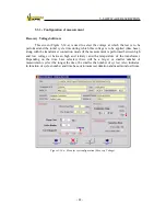
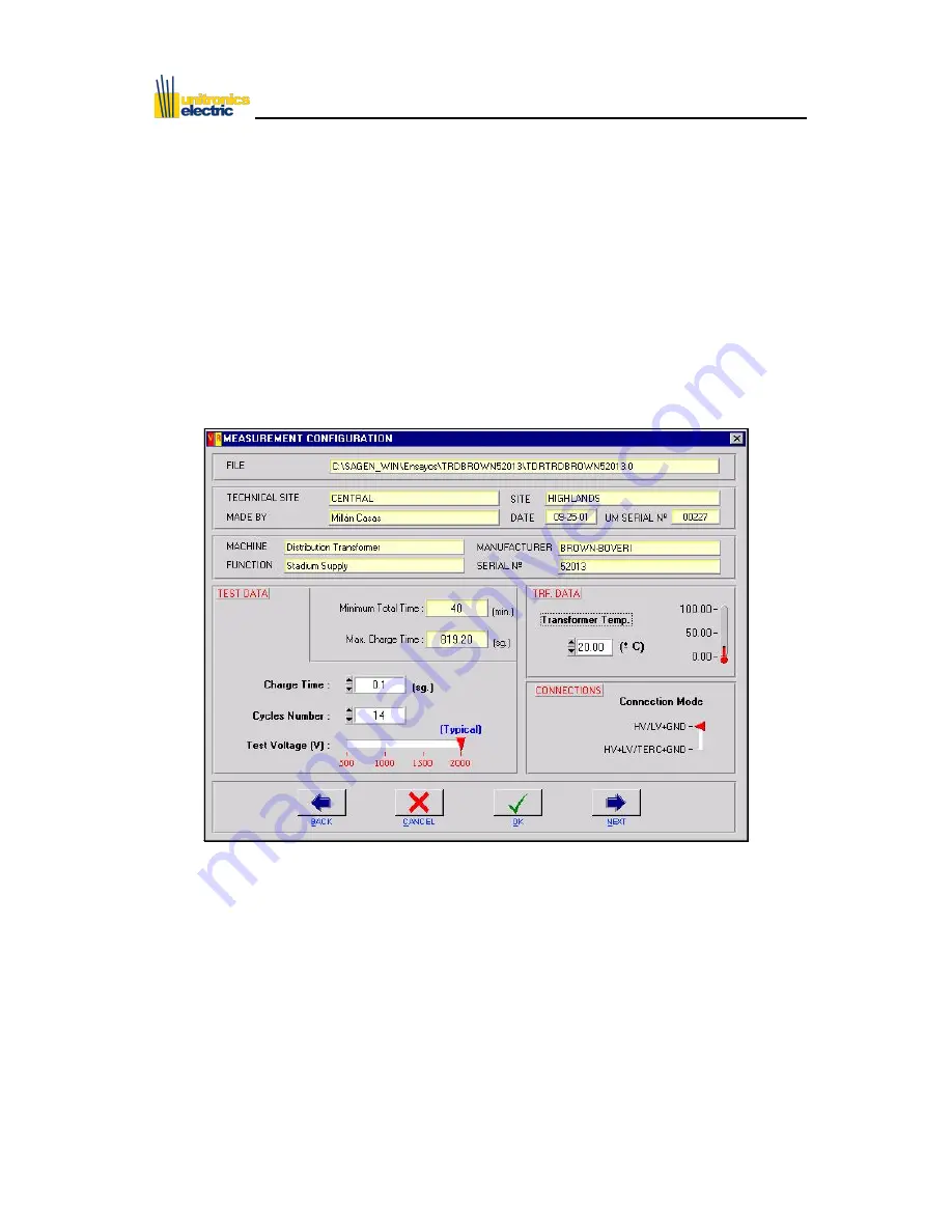
This screen (Figure 5-14-a) is used to select the voltage at which the test is to be
performed and the initial cycle time during which this voltage is to be applied (time base),
along with the transformer connection mode (if the measurement is performed between high
and low voltage or between high and tertiary) and the temperature of the transformer.
Depending on the time base selected, there will be a larger or smaller number of
measurement cycles (the longer the time, the smaller the number of cycles). Also indicates,
in function of cycles number and time base, minimum test duration and maximum load time.
Figure 5-14-a: Menu for test configuration (Recovery Voltage).
Summary of Contents for UM2B
Page 2: ......
Page 67: ...5 SOFTWARE DESCRIPTION 65 Figure 5 46 a First page of the report Recovery Voltage ...
Page 68: ...5 SOFTWARE DESCRIPTION 66 Figure 5 47 a Second page of report Recovery Voltage ...
Page 69: ...5 SOFTWARE DESCRIPTION 67 Figure 5 48 Third page of report Recovery Voltage ...
Page 70: ...5 SOFTWARE DESCRIPTION 68 Figure 5 46 b First page of the report Insulation Resistance ...
Page 71: ...5 SOFTWARE DESCRIPTION 69 Figure 5 47 b Second page of the report Insulation Resistance ...
Page 87: ...8 TECHNICAL SUPPORT 85 Description of fault Materials returned on of of the year Table 8 1 ...
Page 95: ...APPENDIX B CONTROL SOFTWARE 93 APPENDIX A CE CONFORMITY DECLARATION ...

