background image


Unitronics 


I/O Expansion Modules and Adapters


Installation Guide 


SCAN  

 to download 

EX-D16A3-RO8


IO-DI8-RO4


IO-D16A3-RO16


IO-AI4-AO2


EX-D16A3-TO16


IO-DI8-RO8


IO-D16A3-TO16


IO-DI8ACH


EX-A2X


IO-DI8-TO8


IO-DI16


IO-AI8


EX-RC1


IO-RO8


IO-AO6X


IO-LC1


IO-PT400


IO-RO16


IO-ATC8


IO-LC3


IO-PT4K 

IO-TO16 

IO-AI1X-AO3X 


General Description 


The products listed above may be used with compatible Unitronics PLCs. 

Detailed Installation Guides containing the I/O wiring diagrams for these models, technical specifications, 
and additional documentation are located in the Technical Library in the Unitronics website:   

https://unitronicsplc.com/support-technical-library/


Alert Symbols and General Restrictions 

When any of the following symbols appear, read the associated information carefully. 

Symbol 

Meaning 

Description 


Danger 

The identified danger causes physical and property damage. 


Warning 

The identified danger could cause physical and property damage. 

Caution


Caution 

Use caution. 

 Before using this product, the user must read and understand this document.  

 All examples and diagrams are intended to aid understanding, and do not guarantee operation. 

Unitronics accepts no responsibility for actual use of this product based on these examples. 

 Please dispose of this product according to local and national standards and regulations. 

 Only qualified service personnel should open this device or carry out repairs. 


 Failure to comply with appropriate safety guidelines can cause severe injury or property 

damage. 


 Do not attempt to use this device with parameters that exceed permissible levels. 

 To avoid damaging the system, do not connect/disconnect the device when power is on. 


Environmental Considerations 


 Do not install in areas with: excessive or conductive dust, corrosive or flammable gas,  

moisture or rain, excessive heat, regular impact shocks or excessive vibration, in  
accordance with the standards given in the product’s technical specification sheet. 

 Do not place in water or let water leak onto the unit. 

 Do not allow debris to fall inside the unit during installation. 


 Ventilation: 10mm space required between 

controller’s top/bottom edges & enclosure walls. 

 Install at maximum distance from high-voltage cables and power equipment. 


Summary of Contents for EX-D16A3-RO8

Page 1: ...read and understand this document All examples and diagrams are intended to aid understanding and do not guarantee operation Unitronics accepts no responsibility for actual use of this product based on these examples Please dispose of this product according to local and national standards and regulations Only qualified service personnel should open this device or carry out repairs Failure to compl...

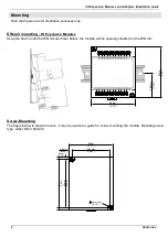
Page 2: ...odules Snap the device onto the DIN rail as shown below the module will be squarely situated on the DIN rail 80mm 3 15 93mm 3 66 44 5mm 1 75 Screw Mounting The figure below is drawn to scale It may be used as a guide for screw mounting the module Mounting screw type either M3 or NC6 32 4mm 5 8mm 0 228 85mm 3 346 80mm 3 15 68 4mm 2 693 93mm 3 66 4mm x2 0 16 0 16 ...

Page 3: ...puts must be rated as SELV PELV Class 2 Limited Power Do not connect either the Neutral or Line signal of the 110 220VAC to device s 0V pin All wiring activities should be performed while power is OFF Use over current protection such as a fuse or circuit breaker to avoid excessive currents into the power supply connection point Unused points should not be connected unless otherwise specified Ignor...

Page 4: ...e that is properly sized for the load Earthing the product To maximize system performance avoid electromagnetic interference as follows Use a metal cabinet Connect the 0V and functional ground points if exist directly to the earth ground of the system Use the shortest less than 1m 3 3 ft and thickest 2 08mm 14AWG min wires possible UL Compliance The following section is relevant to Unitronics prod...

Page 5: ...rence à tous les produits Unitronics portant le symbole UL produits qui ont été certifiés pour une utilisation dans des endroits dangereux Classe I Division 2 Groupes A B C et D Attention Cet équipement est adapté pour une utilisation en Classe I Division 2 Groupes A B C et D ou dans Non dangereux endroits seulement Le câblage des entrées sorties doit être en accord avec les méthodes de câblage se...

Page 6: ...plied including but not limited to any implied warranties of merchantability fitness for a particular purpose or non infringement Unitronics assumes no responsibility for errors or omissions in the information presented in this document In no event shall Unitronics be liable for any special incidental indirect or consequential damages of any kind or any damages whatsoever arising out of or in conn...

Reviews: