background image


Unitronics 


IO-D16A3-RO16 

XL I/O Expansion Module 
Installation Guide 

The Unitronics

®

 IO-D16A3-RO16 is an XL I/O expansion module for use in conjunction with specific Unitronics controllers.  

XL modules comprise enhanced I/O configurations and detachable I/O connectors. A local or remote I/O adapter module is 
required to interface between the expansion module and the PLC controller and provide power to the expansion modules in the 
system. 

The I/O expansion module provides: 

ƒ

  16 digital inputs, including 2 HSC 

ƒ

  3 analog inputs 

ƒ

  16 relay outputs 

For additional information and technical specifications, visit the Technical Library at 

0H

www.unitronics.com

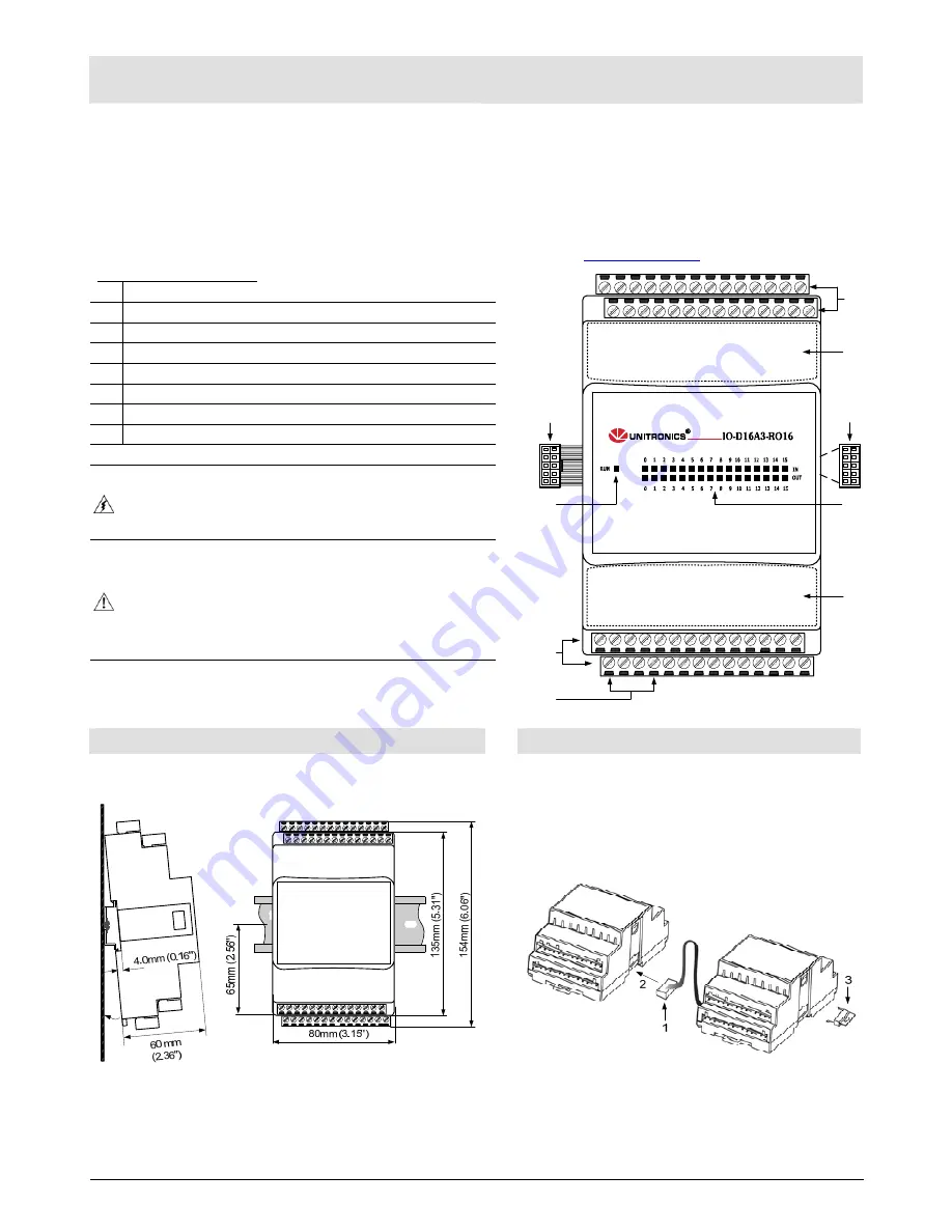
Component Identification 

1 Module-to-module 

connector 

2 Status 

indicator 

3 Output 

connectors 

Output power supply connection points 

I/O address labels (provided with module) 

Input/output status indicators 

Module-to-module connector port 

8 Input 

connectors 


ƒ

  Failure to comply with appropriate safety guidelines can 

cause severe personal injury or damage to property. 


ƒ

  Only qualified personnel should service and operate this 

device. 

ƒ

  When power is turned on, do not connect or disconnect the 

device to avoid damaging the system. 


8

7

4

1

2

6

3

5

5


Mounting the Module 


Connecting Modules 

To mount the module on a 35mm DIN-rail, snap it squarely onto 
the DIN-rail, as shown below. 


To connect a module to the adapter or expansion module:

1. Push the module-to-module connector (1) into the port 

(2) located on the right side of the module or adapter. 

2. Push the protective cap (3) into the connector port of 

the last module. The cap is supplied with the adapter. 


ƒ

  Install the module in an upright position. 

ƒ

  To ensure good ventilation, leave at least 50mm between the 

device and all other objects above or below it. 

ƒ

  Install at a maximum distance from high-voltage cables and 

power equipment. 


Summary of Contents for IO-D16A3-RO16

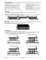
Page 1: ...ided with module 6 Input output status indicators 7 Module to module connector port 8 Input connectors Failure to comply with appropriate safety guidelines can cause severe personal injury or damage to property Only qualified personnel should service and operate this device When power is turned on do not connect or disconnect the device to avoid damaging the system 8 7 4 1 2 6 3 5 5 Mounting the M...

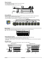
Page 2: ...in n p Output connector pins V 0V C0 C1 Ensure that the total current drain on any single line does not exceed 10A If a specific pin requires more than 10A connect it with a separate wire The following diagram demonstrates the wiring options Wiring Inputs The following diagram shows the input connectors with pin numbers and corresponding LED numbers Note Where input numbers are stated the intentio...

Page 3: ...ries daisy chain To facilitate this use both the RG pins Wiring Outputs The following diagram shows the output connectors with pin numbers and corresponding LED numbers Note Where output numbers are stated the intention is the LED number Wiring the Output Power Supply A non isolated power supply can be used provided that the 0V signal is connected to the earth ground Do not connect the neutral or ...

Page 4: ... module is supplied with a set of labels select the label appropriate to the position of the module For more information refer to the Configuring I O Expansion Modules topic in the on line help of the software supplied with the controller The information in this document reflects products at the date of printing Unitronics reserves the right subject to all applicable laws at any time at its sole d...

Reviews: