background image

Unitronics 

IO-DI8-RO8, IO-DI8-RO8-L  

 I/O Expansion Modules  8 Inputs, 8 Outputs

The IO-DI8-RO8 and IO-DI8-RO8-L are I/O 
expansion modules that can be used in 
conjunction with specific Unitronics OPLC 
controllers. 
The modules are identical except for their 
voltage specifications: IO-DI8-RO8 runs at 
24 VDC; IO-DI8-RO8-L at 12 VDC. 
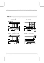
Both modules offer 8 digital inputs, type 
pnp/npn (source/sink), and 8 relay outputs. 
The interface between a module and the 
OPLC is provided by an adapter. 
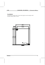
These modules may either be snap-
mounted on a DIN rail, or screw-mounted 
onto a mounting plate.


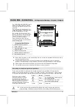
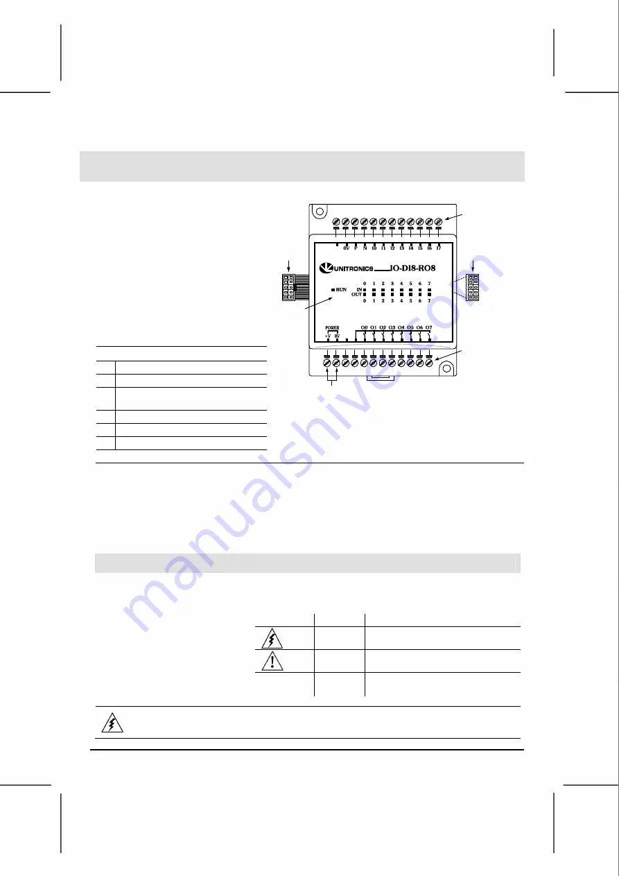
Component identification 

1 Module-to-module 

connector 

2 Status 

indicators 

Connection points for power  
supply to outputs 

Output connection points 

Module-to-module connector port 

Input connection points 

1

5

6

4

2

3

„

Before using this product, it is the responsibility of the user to read and understand this document and any
accompanying documentation.

„

All examples and diagrams shown herein are intended to aid understanding, and do not guarantee
operation.  Unitronics accepts no responsibility for actual use of this product based on these examples.

„

Please dispose of this product in accordance with local and national standards and regulations.

„

Only qualified service personnel should open this device or carry out repairs.

User safety and equipment protection guidelines 

This document is intended to aid trained and competent personnel in the installation of this equipment as 
defined by the European directives for machinery, low voltage, and EMC.  Only a technician or engineer trained 
in the local and national electrical standards should perform tasks associated with the device’s electrical wiring. 

Symbol Meaning 

Description 

Danger 

The identified danger causes physical 
and property damage. 

Warning 

The identified danger can cause 
physical and property damage. 

Symbols are used to highlight 
information relating to the user’s 
personal safety and equipment 
protection throughout this document.  
When these symbols appear, the 
associated information must be read 
carefully and understood fully. 

Caution


Caution Use 

caution. 

„

Failure to comply with appropriate safety guidelines can result in severe personal injury or
property damage.  Always exercise proper caution when working with electrical equipment.

Summary of Contents for IO-DI8-RO8-L

Page 1: ...itronics accepts no responsibility for actual use of this product based on these examples Please dispose of this product in accordance with local and national standards and regulations Only qualified service personnel should open this device or carry out repairs User safety and equipment protection guidelines This document is intended to aid trained and competent personnel in the installation of t...

Page 2: ...derations Do not install in areas with excessive or conductive dust corrosive or flammable gas moisture or rain excessive heat regular impact shocks or excessive vibration Leave a minimum of 10mm space for ventilation between the top and bottom edges of the device and the enclosure walls Do not place in water or let water leak onto the unit Do not allow debris to fall inside the unit during instal...

Page 3: ...odules Unitronics 3 Screw Mounting The figure below is not drawn to scale It may be used as a guide for screw mounting the module Mounting screw type either M3 or NC6 32 4mm 5 8mm 0 228 85mm 3 346 80mm 3 15 68 4mm 2 693 93mm 3 66 4mm x2 0 16 0 16 ...

Page 4: ...k all wiring before turning on the power supply Wiring Procedures Use crimp terminals for wiring use 26 12 AWG wire 0 13 mm 2 3 31 mm 2 for all wiring purposes 1 Strip the wire to a length of 7 0 5mm 0 250 0 300 inches 2 Unscrew the terminal to its widest position before inserting a wire 3 Insert the wire completely into the terminal to ensure that a proper connection can be made 4 Tighten enough ...

Page 5: ...ource or npn sink inputs npn sink inputs pnp source inputs 0V V Circuit Protection Device 0V V npn sink high speed counter frequency measurer pnp source high speed counter frequency measurer 0V V Circuit Protection Device High speed Counter Reset High speed Counter 0V V High speed Counter Reset High speed Counter ...

Page 6: ...ormity to voltage power supply specifications connect the device to a regulated power supply Notes 1 The adapter and output s power supply must be connected to the same 0V signal Outputs Circuit Protection Device L1 L2 L3 115 230VAC V 12 24VDC Output s power supply 0V V N 0V Load See Note 1 Increasing Contact Life Span Both modules have 8 relay outputs To increase the life span of these contacts a...

Page 7: ...Logic 0 0 3VDC 4 3mA for Logic 1 Input current 6mA 24VDC 6mA 12VDC Response time 10mSec typical Input 7 The specifications below apply when this input is wired for use as a high speed counter input frequency measurer See Notes 2 and 3 Resolution 16 bit Frequency 5kHz maximum Minimum pulse width 80µs Outputs Number of outputs 8 relay Output type SPST NO Form A All relays share a common signal Isola...

Page 8: ... number indicates the I O s location in the system This number relates to both the position of the expansion module in the system and to the position of the I O on that module Expansion modules are numbered from 0 7 as shown in the figure below 0 1 2 3 4 5 6 7 Expansion module identification number Adapter The formula below is used to assign addresses for I O modules used in conjunction with the O...

Reviews: