

IO-RO16, IO-RO16-L
I / O E x p a n s i o n M o d u l e s
5/03
6
Unitronics Industrial Automation
IO-RO16, IO-RO16-L Technical Specifications
Max. current consumption
60mA maximum from the adapter’s 5VDC
Typical power consumption
0.18W @ 5VDC
Status indicator
(RUN)
Green LED:
—Lit when a communication link is established between module and OPLC.
—Blinks when the communication link fails.
Outputs
Number of outputs
16 relay ( in two groups)
Output type
SPST-NO relay; 230VAC / 12/24 VDC
Type of relay
IO-RO16
Fujitsu (Takamisawa) NY-24W-K or NAIS (Matsushita) PA1a-24V
IO-RO16L
Fujitsu (Takamisawa) NY-12W-K or NAIS (Matsushita) PA1a-12V
Isolation
By relay
Status Indicators
(O0 to O15)
Red LEDs—Lit when the corresponding output is active.
Output current
Resistive Load
3A maximum per output
8A maximum total for common. See Note 1.
Inductive Load
1A maximum per output
4A maximum total for common. See Note 1
Maximum frequency
10Hz
Contact protection
External precautions required (see above: Increasing Contact Life Span)
Outputs’ power supply: IO-RO16
Nominal operating voltage
24VDC
Operating voltage
20.4 to 28.8VDC
Maximum current consumption
132mA@24VDC
Outputs’ power supply: IO-RO16-L
Nominal operating voltage
12VDC
Operating voltage
10.2 to 15.6VDC
Maximum current consumption
176mA@12VDC
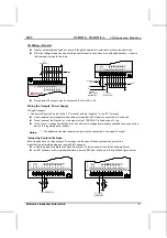
Notes:
1.
Each group of 8 outputs share a common signal.
Environmental
IP20 / NEMA1
Operating temperature
0
°
to 50
°
C (32
°
to 122
°
F)
Storage temperature
-20
°
to 60
°
C (-4
°
to 140
°
F)
Relative Humidity (RH)
5% to 95% (non-condensing)
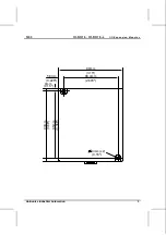
Dimensions (WxHxD)
80mm x 93mm x 60mm (3.15” x 3.66” x 2.362”)
Weight
125g (4.25 oz.)
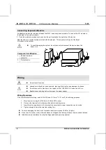
Mounting
Either onto a 35mm DIN-rail or screw- mounted.


