

Unitronics
1
V200-18-E5B
Snap-in I/O Module
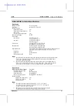
The V200-18-E5B
plugs directly into the
back of compatible
Unitronics OPLCs,
creating a self-
contained PLC unit
with a local I/O
configuration.
Features
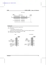
18 isolated digital inputs, includes 2 H.S.C inputs, type pnp/npn
(source/sink)
15 isolated pnp (source) outputs
2 isolated pnp/npn (source/sink) transistor outputs, includes 2 H.S. outputs
3
analog
inputs
Before using this product, it is the responsibility of the user to read and understand this document
and any accompanying documentation.
All examples and diagrams shown herein are intended to aid understanding, and do not guarantee
operation. Unitronics accepts no responsibility for actual use of this product based on these
examples.
Please dispose of this product in accordance with local and national standards and regulations.
Only qualified service personnel should open this device or carry out repairs.
User safety and equipment protection guidelines
This document is intended to aid trained and competent personnel in the installation of this equipment as
defined by the European directives for machinery, low voltage, and EMC. Only a technician or engineer trained
in the local and national electrical standards should perform tasks associated with the device’s electrical wiring.
Symbol Meaning
Description
Danger
The identified danger causes physical
and property damage.
Warning
The identified danger can cause
physical and property damage.
Symbols are used to highlight
information relating to the user’s
personal safety and equipment
protection throughout this document.
When these symbols appear, the
associated information must be read
carefully and understood fully.
Caution
Caution
Use caution.
Failure to comply with appropriate safety guidelines can result in severe personal
injury or property damage. Always exercise proper caution when working with
electrical equipment.
Check the user program before running it.
Do not attempt to use this device with parameters that exceed permissible levels.
Install an external circuit breaker and take appropriate safety measures against short-
circuiting in external wiring.
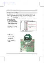
To avoid damaging the system, do not connect / disconnect the device when the
power is on.
Caution
Ascertain that terminal blocks are properly secured in place.
Environmental Considerations
Do not install in areas with: excessive or conductive dust, corrosive or flammable gas,
moisture or rain, excessive heat, regular impact shocks or excessive vibration.
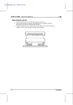
Provide proper ventilation by leaving at least 10mm of space between the top and
bottom edges of the device and the enclosure walls.
Do not place in water or let water leak onto the unit.
Do not allow debris to fall inside the unit during installation.
i4 Automation Ltd - 01480 395256


