Page 8 of 43
Page 9 of 43
MAN.SCPSCU.REVD.03022015
Installation
THE SUPPLY POWER CIRCUIT MUST INCLUDE AN OVERPROTECTION DEVICE WITH A MAXIMUM
RATING OF 20 A. A DISCONNECT SWITCH MUST BE LOCATED IN CLOSE PROXIMITY TO THE
COOLER. IF THE EQUIPMENT IS USED IN A MANNER NOT SPECIFIED BY THE MANUFACTURER,
THE PROTECTION PROVIDED BY THE EQUIPMENT MAY BE IMPAIRED PER CLAUSE 5.4.4(I) IN
STANDARD EN 61010-1.
Installation shall be in accord with the facility requirements. Tampering and replacement with non-factory components
may adversely affect the safe use of the system.
Thermoelectric Sample Coolers should be installed away from heat sources in a well ventilated area of an instrument
rack or enclosure. The Cooler relies on the ambient temperature as a coolant, too high a level will cause it to perform
unreliably. Contact the factory for recommendations.
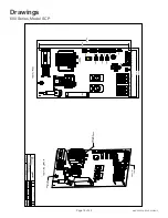
The sample has mounting taps on the top and bottom to allow it to be wall mounted or mounted to rails in an instrument
rack.
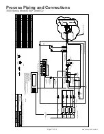
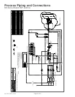
Sample line should be brought to the tubing fitting that is provided at the top of the first heat exchanger as the sample
inlet. The dry sample outlet from the cooler is the 1/4” tubing fitting coming out of the top of the flow meters located at
the top of the panel.
Calibration gas connections are 1/4" tube fittings located at the manifold at the top of the sample conditioning panel.
Calibration gas out connection to probe filter is located on the flow meter panel.
All flow meter connections are 1/4" tube fittings.
The drain connection is a 3/8" tube fitting located at the bottom of the sample conditioning panel. Moisture should be
observed at the drain from the cooler when a steady state condition is established.
There must be a method to remove the condensate from the panel. A drain line from the peristaltic pump, outlet must be
run to sewer, a container, or to the ground outside the instrument enclosure to avoid collecting water (condensate) on
the floor.

