background image

Page 6 of 43

Page 7 of 43

MAN.SCPSCU.REVD.03022015

Description and Principle of Operation

APPLICATION

In order to analyze combustion products or incinerator effluents utilizing a direct extractive sampling technique, it is 

important to remove the water vapor without removing the water soluble fraction(s) from the gas sample. The heat 

exchangers (impingers) used in the Universal Analyzers gas sample coolers are designed to minimize the gas/condensate 

area and time of contact to reduce to a minimum, the amount of mass transfer of those water soluble components from 

the gas phase into the liquid phase. The result is a dry gas sample which has the same composition on a dry basis before 

and after passing through the chiller.

A gas sample is usually taken from a stack with a probe extending into the stack. The heated probe filter is maintained at 

a temperature above the dew point of the stack gas, usually 300

°F

 to 400

°

F (149°C to 204°C), in order to avoid cementing 

the filtered particulates to the filter medium with condensate. A means is usually provided to automatically blow the 

particulates trapped by the filter back into the stack on a periodic basis. 

The stack gas sample is clean but “wet” after passing through the filter assembly. The moisture in the gas sample comes 

from the fuel as a product of combustion, from the humidity in the air which supports the combustion and from the water 

content which was trapped in the fuel. This latter source of water in the sample can be from burning moist coal, wet 

garbage, or from water injected into the fire box. Water from all of these sources will remove the water soluble gases 

from the sample stream if allowed to condense in the sample line prior to the controlled separation within the Universal 

Analyzers’ heat exchangers in the sample cooler.

In order to maintain the temperature of the gas sample above the dew point as it is transported to the gas sample cooler, 

a heat traced sample line is usually employed. The heat traced sample line can be very short if the gas sample cooler is 

located close to the heated stack filter or it could be several hundred feet long if the gas sample cooler is located in the 

analyzer shack some distance from the stack.

The Universal Analyzers gas sample cooler contains the special impinger type heat exchanger(s). These are mounted 

within heat transfer blocks which are cooled by thermoelectric elements utilizing the “Peltier Effect” discovered in 

France over half a century ago. Where high water contents are encountered, it is efficient to remove the condensate 

in two stages, one at the temperature of the air in the vicinity of the “Precooler” and then by passing the sample into 

a heat exchanger cooled by the thermoelectric elements. The precooler can remove water which will condense at the 

temperature of the environment. In high water content samples, this could be as much as 80% of the water in the sample. 

The thermo-electrically cooled stage is temperature controlled at a factory setting of 4°C (39°F). 

The gas sample conditioning system contains additional components to insure that a clean, dry sample is presented to the 

analyzer for minimum analyzer maintenance. The water carry over sensor with filter (WCSF) provides the opportunity to 

detect if moisture has traveled past the cooler and alarms to indicate a problem with a part of the sample system (possibly, 

but not limited to the cooler). The WCSF consists of a coalescing filter (ceramic standard), transparent bowl, and 

capacitance sensor. The capacitive sensor allows for detection of any liquid or solid that has passed into the transparent 

bowl, including distilled water with no ions present.

DESCRIPTION

The key to the success of the Universal Analyzers Sample Cooler is being able to condense the water from a wet gas 

sample with a minimal loss of the water soluble gas fraction is due to the design of the heat exchanger. Please refer to 

Drawings P0147 and P0149. The separation occurs in a classical impinger which has a highly polished cylindrical surface 

cooled to the desired dew point temperature. The hot wet sample is brought to the bottom of the cylinder through an 

insulated tube and allowed to rise through a narrow annular area at a relatively high Reynolds number to insure the entire 

sample is influenced by the cold surface. The condensate falls down the cold polished surface in the form of a sheet 

(as opposed to droplets or the bubbling of the gas sample through the condensate) which minimizes the surface area in 

contact with the gas sample.

Summary of Contents for SCP

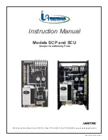
Page 1: ...MAN SCPSCU REVD 03022015 Instruction Manual Models SCP and SCU Sample Conditioning Plate 5200 Convair Drive Carson City NV 89706 Phone 775 883 2500 Fax 775 883 6388 www universalanalyzers com ...

Page 2: ...age 3 Definition of Symbols 4 Specifications 5 Description and Principle of Operation 6 Installation 8 Electrical Connections 9 Process and Piping Connections 10 Start Up 13 Shutdown 13 Maintenance 14 Troubleshooting 16 Spare Parts 17 Drawings 19 Limited Warranty 41 ...

Page 3: ...ies included with it immediately on arrival by removing them from the packing and checking for missing components against the packing list Check the items for any damage in transit and if required inform the shipping insurance company immediately of any damage found Storage Location should be protected from the elements Although all components provided are designed to resist corrosion additional p...

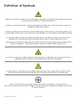
Page 4: ...ER THE PROTECTION PROVIDED BY THE EQUIPMENT MAY BE IMPAIRED PER CLAUSE 5 4 4 i IN STANDARD EN 61010 1 CAUTION RISK OF DANGER SYMBOL INDICATES INJURY MAY OCCUR IF MANUFACTURER S INSTRUCTIONS ARE NOT ADHERED TO PLEASE READ MANUAL CAREFULLY WHEN SYMBOL IS DISPLAYED CAUTION HOT SURFACE SYMBOL INDICATES EXPOSED SURFACE TEMPERATURE CAN CAUSE BURNS OR PERSONAL INJURY CARE SHOULD BE TAKEN WHEN CONTACT IS ...

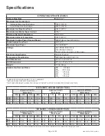
Page 5: ... 25 C AMBIENT SEE GAS COOLER CAPACITY CHART BELOW WATTAGE DEPENDANT ON SELECTED COOLER CONTACT FACTORY FOR SELECTED COOLER WATTAGE 3000 SERIES COOLER CAPACITY DATA Ambient 77 F 25 C Water Vapor Ambient 90 F 25 C Water Vapor Ambient 105 F 25 C Water Vapor 12 15 30 50 12 15 30 50 12 15 30 50 3040 5 l m 4 l m 2 8 l m 1 4 l m 5 l m 4 l m 2 l m 1 l m 2 8 l m 2 4 l m 1 2 l m 0 6 lm 3050 8 l m 8 l m 7 l ...

Page 6: ...n the analyzer shack some distance from the stack The Universal Analyzers gas sample cooler contains the special impinger type heat exchanger s These are mounted within heat transfer blocks which are cooled by thermoelectric elements utilizing the Peltier Effect discovered in France over half a century ago Where high water contents are encountered it is efficient to remove the condensate in two st...

Page 7: ... alarm position The DRY lamp indicates that there is no water in contact with the moisture sensor listed as WCSF If the DRY lamp is out the alarm relay will be in the alarm position The alarm relay is a single relay activated by either of the above alarm conditions The alarm relay is energized in the safe condition and will relax into the de energized alarm position if a fault is detected If a bro...

Page 8: ...g taps on the top and bottom to allow it to be wall mounted or mounted to rails in an instrument rack Sample line should be brought to the tubing fitting that is provided at the top of the first heat exchanger as the sample inlet The dry sample outlet from the cooler is the 1 4 tubing fitting coming out of the top of the flow meters located at the top of the panel Calibration gas connections are 1...

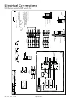
Page 9: ...RE SIZE SHALL BE 18 AWG UNLESS OTHERWISE SPECIFIED COLOR CODE SHALL BE AS FOLLOWS 115VAC 230VAC HOT BLACK L1 BROWN NEUTRAL WHITE L2 BLUE GROUND GREEN G GREEN 3 DC WIRING SHALL BE INDIVIDUAL CONDUCTORS OF STRANDED TINNED COPPER WITH 300V TYPE TFE INSULATION MINIMUM WIRE SIZE SHALL BE 22 AWG UNLESS OTHERWISE SPECIFIED 115VAC 230VAC COLOR CODE SHALL BE AS FOLOOWS V RED VDC RED 0V BLUE VDC BLACK FIELD...

Page 10: ...B1 12 TB1 6 TB1 7 SV4 SV5 SV6 SV7 SV8 SV9 TB5 1 TB5 2 TB5 3 TB5 4 TB5 5 TB5 6 TB5 7 TB5 8 TB5 9 TB5 10 TB5 11 TB5 12 7 8 9 10 11 12 SV7 SV8 SV9 SV7 SV8 SV9 TB1 8 TB1 9 TB1 10 24VDC SOLENOIDS CALIBRATION GASES TB4 SV1 SV2 SV3 1 2 3 4 5 6 SV1 SV2 SV3 SV1 SV2 SV3 TB1 2 TB1 12 TB1 3 TB1 4 TB4 1 TB4 2 TB4 3 TB4 4 TB4 5 TB4 6 SSR1 4 24VDC SOLENOIDS SWITCHING BLOCK OPTIONAL TB2 8 TB2 7 TB2 4 TB2 3 PS2 CA...

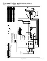
Page 11: ... 3050 230Vac 8200 0008 0000 0000 4958 0028 4958 0045 1 1 1 1 1 1 2 2 1 2 6 1 1 4 1 1 1 1 1 1 1 CALIBRATION GASES 6 MAXIMUM CALIB GAS TO PROBE STACK FLOW CG1 SV4 FI 0 2 5 L MIN SAMPLE TO ANALYZER INSTR AIR 90 PSIG 40 F DEWPOINT CALIB GAS SAMPLE SV2 SV3 SV1 GAS BLOCK BLEED 3 WAY SOLENOID PRESSURE SAMPLE CALIB PI 2 VACCUM PUMP PI 1 SYSTEM CALIBRATION 2 WAY SOLENOID CALIBRATION SAMPLE DIRECT 3 WAY SOL...

Page 12: ... REV REVISIONS FOR PART NO M Walser APVD BY DRAWN BY DRAWING NO DATE P ID DATE DESCRIPTION DWN APVD SCALE SIZE SHEET NTS D 3 OF 5 ECO 3 WAY VALVE TYPICAL NC C NO LEGEND 2 WAY NORMALLY CLOSED NOTES 1 ALL FITTINGS 1 4 TUBE UNLESS OTHERWISE NOTED BULKHEAD FITTING FOR REFERENCE ONLY PI 4 20MA BYPASS 2 5 P1 PI AIT 09 18 2013 09 18 13 Initial Release MY MW 1801 M Withrow BLEED OUT OPTIONAL OPTIONAL CG5 ...

Page 13: ...t If additional or reduced pressure is required there is an adjustable pressure regulator located at the pump The green DRY LED light will be on at start up The light will go out and the alarm relay de energized when the sensor detects condensate A test can be performed by putting water on the moisture sensor The sample pump is powered through the alarm relay contacts it will cease running When th...

Page 14: ...com INSTALLING OR REPLACING HEAT EXCHANGERS REMOVING THE HEAT EXCHANGER 1 Remove the inlet and outlet tubes by loosening the compression fittings Always use a backup wrench on the fitting body to ensure no damage to the heat exchanger occurs 2 Remove the drain fitting using the same procedure as the inlet outlet Remove the drain fittings from the exchanger Use a backup wrench on the lower heat exc...

Page 15: ...ly in front of the blower is the inlet side of the heat sink Using a soft bristled brush gently remove to debris from the heat sink Alternatively a computer safe aerosol cleaner can be used to remove the debris Clean any loose debris from the enclosure and blower motor using a vacuum or compressed air Replace all connectors reference electrical drawings below for details Reinstall the side pane CL...

Page 16: ...and ensure air movement High oxygen readings low pollutant readings Leak Loose connection Verify all fittings are leak free Defective peristaltic pump tubing Replace tubing Broken or leaking heat exchanger Remove heat exchanger and replace if broken or repair replace O Ring if leaking Dry light is not Illuminated Water carry over Faulty water carry over device or circuit board See Water Carry Over...

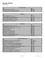
Page 17: ...28 Peristaltic Pump Motor 230VAC 12 RPM 4958 0045 Blower Motor Squirrel Cage 115VAC 5209 0049 Blower Motor Squirrel Cage 230VAC 5209 0099 Insulation Kit Heat Transfer Block Model 3040 3050 9515 0042 Insulation Kit Heat Transfer Block Model 3080 9515 0023 Temperature Sensor Assembly AD592 1150 0017 Optional Parts Accessories Part P N Solid State Relay 3 32VDC 240VAC 25 Amp Sample Pump 3152 0002 WCO...

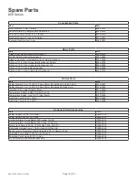
Page 18: ...ement Pair 15VDC 8 5 Amp 40mm Models 622 632 643 644 3016 0001 Peltier Element Pair 15VDC 3 9 Amp 30mm Models 624 634 Only 3016 0003 Insulation Kit for Heat Transfer Block 9515 0024 Temperature Sensor AD592 Chiller Control 1150 0017 Temperature Switch Limit 185 F Over Temp 3103 0006 Heat Sink Cooling Fan 12VDC 4800 0002 Heat Sink Cooling Fan 24VDC 4800 0008 Optional Parts Accessories Part P N Powe...

Page 19: ...G NO DATE 600 SCP INT Model 600 Series Layout Dimensions DATE DESCRIPTION DWN APVD SCALE SIZE SHEET NTS D 1 OF 5 09 18 13 Initial Release MY MW ECO 1801 ISOMETRIC VIEW P1 P2 WCOF M Withrow PI 1 PI 2 MODEL 600 CG1 2 3 4 5 6 SYS CAL FM1 FM2 FM3 FM4 SPC1 20 3 4 38 1 2 19 1 8 36 1 2 FM5 VENT 1 4 TUBE DRAIN 1 4 TUBE SAMPLE INLET 3 8 TUBE P S1 5200 Convair Drive Carson City NV 89706 PH 775 883 2500 FAX ...

Page 20: ...ING PLC OR DATA LOGGER 1 CALIBRATION SAMPLE SELECT 2 CALIBRATION GAS SELECT 3 SYSTEM DIRECT CALIBRATION SELECT SYSTEM BIAS CALCULATION 4 PROBE BLOW BACK 5 PROBE LOW TEMPERATURE ALARM 6 CHILLER MALFUNCTION HIGH TEMPERATURE OR WATER CARRY OVER 7 HIGH INLET VACUUM PROBE FILTER INITIATE BLOWBACK OR MAINTENANCE 8 SAMPLE CALIB GAS PRESS LOW ALARM FOR MANTENANCE CALIBRATION GASES 6 MAXIMUM CALIB GAS TO P...

Page 21: ...OR PART NO M Walser APVD BY DRAWN BY DRAWING NO DATE P ID DATE DESCRIPTION DWN APVD SCALE SIZE SHEET NTS D 3 OF 5 ECO 3 WAY VALVE TYPICAL NC C NO LEGEND 2 WAY NORMALLY CLOSED NOTES 1 ALL FITTINGS 1 4 TUBE UNLESS OTHERWISE NOTED BULKHEAD FITTING FOR REFERENCE ONLY PI 4 20MA BYPASS 2 5 P1 PI AIT 09 18 2013 09 18 13 Initial Release MY MW 1801 M Withrow BLEED OUT OPTIONAL OPTIONAL CG5 CG6 SV8 SV9 P201...

Page 22: ... MIN CHANNELS 1 VS1 PS1 SET 5 psi PS2 LIQUID DRAIN 1 A 2 A FM1 FM2 FM3 FM5 SV5 SV6 SV7 SYS CAL R1 P2 INLET 3 8 TUBE S SNUBBER S SNUBBER SET 5psi SET 10psi SET 7hg NOTES 1 ALL FITTINGS 1 4 TUBE UNLESS OTHERWISE NOTED FOR REFERENCE ONLY PI 4 20MA 0 2 5 L MIN BYPASS 2 3 5 P1 PI AIT AIT BLEED OUT OPTIONAL OPTIONAL CG5 CG6 SV8 SV9 3 WAY VALVE TYPICAL NC C NO LEGEND 2 WAY NORMALLY CLOSED BULKHEAD FITTIN...

Page 23: ...34 08 12 2014 600 Series REV REVISIONS FOR PART NO M Walser APVD BY DRAWN BY DRAWING NO DATE 600 SCU INT DATE DESCRIPTION DWN APVD SCALE SIZE SHEET NTS D 1 OF 5 08 12 14 Initial Release MY MW ECO 2089 M Withrow 5200 Convair Drive Carson City NV 89706 PH 775 883 2500 FAX 775 883 6388 TB3 TB4 TB5 PI 1 PI 2 R1 B B PS2 CG1 2 3 4 5 6 SYS CAL FM1 FM2 FM3 FM4 SSR1 ISOMETRIC VIEW SAMPLE INLET 3 8 TUBE 12 ...

Page 24: ...7 4965 0018 4965 0008 624 8200 0008 0000 0000 4958 0028 4958 0045 1 1 1 1 1 1 2 2 1 2 6 1 1 2 1 1 1 1 1 1 PLC OR DATA LOGGER 1 CALIBRATION SAMPLE SELECT 2 CALIBRATION GAS SELECT 3 SYSTEM DIRECT CALIBRATION SELECT SYSTEM BIAS CALCULATION 4 PROBE BLOW BACK 5 PROBE LOW TEMPERATURE ALARM 6 CHILLER MALFUNCTION HIGH TEMPERATURE OR WATER CARRY OVER 7 HIGH INLET VACUUM PROBE FILTER INITIATE BLOWBACK OR MA...

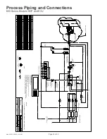
Page 25: ...45 1 1 1 1 1 1 2 2 1 2 6 1 1 3 1 1 1 1 1 1 CALIBRATION GASES 6 MAXIMUM CALIB GAS TO PROBE STACK FLOW CG1 SV4 FI 0 2 5 L MIN SAMPLE TO ANALYZER INSTR AIR 90 PSIG 40 F DEWPOINT CALIB GAS SAMPLE SV2 SV3 SV1 GAS BLOCK BLEED 3 WAY SOLENOID PRESSURE SAMPLE CALIB PI 2 VACCUM PUMP PI 1 SYSTEM CALIBRATION 2 WAY SOLENOID CALIBRATION SAMPLE DIRECT 3 WAY SOLENOID 0 10 L MIN FI CG2 CG3 CG4 CALIBRATION GAS SELE...

Page 26: ...GULATOR SAMPLE CONDITIONING U BRACKET SAMPLE FLOWMETERS AIT VENT 4 20MA AIT OUTPUT VOLTAGE CURRENT PLC PRESSURE SWITCH LOSS CALIB GAS 0 2 5 L MIN FI FI 0 5 L MIN CHANNELS 1 VS1 PS1 SET 5 psi PS2 LIQUID DRAIN 1 A 2 A FM1 FM2 FM4 SV5 SV6 SV7 SYS CAL R1 P2 INLET 3 8 TUBE S SNUBBER S SNUBBER SET 5psi SET 10psi SET 7hg FOR REFERENCE ONLY PI 4 20MA BYPASS 2 5 P1 PI AIT BLEED OUT OPTIONAL OPTIONAL CG5 CG...

Page 27: ...PECIFIED COLOR CODE SHALL BE AS FOLLOWS 115VAC 230VAC HOT BLACK L1 BROWN NEUTRAL WHITE L2 BLUE GROUND GREEN G GREEN 3 DC WIRING SHALL BE INDIVIDUAL CONDUCTORS OF STRANDED TINNED COPPER WITH 300V TYPE TFE INSULATION MINIMUM WIRE SIZE SHALL BE 22 AWG UNLESS OTHERWISE SPECIFIED 115VAC 230VAC COLOR CODE SHALL BE AS FOLOOWS V RED VDC RED 0V BLUE VDC BLACK FIELD TO WIRE G 2 1 TB4 SSR2 2 PS 1 J2 SAMPLE P...

Page 28: ...000 Series Layout Dimensions DATE DESCRIPTION DWN APVD SCALE SIZE SHEET NTS D 1 OF 5 09 18 13 Initial Release MY MW ECO 1801 ISOMETRIC VIEW P1 P2 WCOF M Withrow PI 1 PI 2 MODEL 3000 CG1 2 3 4 5 6 SYS CAL FM1 FM2 FM3 FM4 SPC1 20 3 4 38 1 2 19 1 8 36 1 2 FM5 VENT 1 4 TUBE SAMPLE INLET 3 8 TUBE DRAIN 1 4 TUBE 5200 Convair Drive Carson City NV 89706 PH 775 883 2500 FAX 775 883 6388 Drawings 3000 Serie...

Page 29: ...LOSED BULKHEAD FITTING PLC OR DATA LOGGER 1 CALIBRATION SAMPLE SELECT 2 CALIBRATION GAS SELECT 3 SYSTEM DIRECT CALIBRATION SELECT SYSTEM BIAS CALCULATION 4 PROBE BLOW BACK 5 PROBE LOW TEMPERATURE ALARM 6 CHILLER MALFUNCTION HIGH TEMPERATURE OR WATER CARRY OVER 7 HIGH INLET VACUUM PROBE FILTER INITIATE BLOWBACK OR MAINTENANCE 8 SAMPLE CALIB GAS PRESS LOW ALARM FOR MANTENANCE CALIBRATION GASES 6 MAX...

Page 30: ...8 0045 1 1 1 1 1 1 2 2 1 2 6 1 1 4 1 1 1 1 1 1 1 CALIBRATION GASES 6 MAXIMUM CALIB GAS TO PROBE STACK FLOW CG1 SV4 FI 0 2 5 L MIN SAMPLE TO ANALYZER INSTR AIR 90 PSIG 40 F DEWPOINT CALIB GAS SAMPLE SV2 SV3 SV1 GAS BLOCK BLEED 3 WAY SOLENOID PRESSURE SAMPLE CALIB PI 2 VACCUM PUMP PI 1 SYSTEM CALIBRATION 2 WAY SOLENOID CALIBRATION SAMPLE DIRECT 3 WAY SOLENOID 0 10 L MIN FI CG2 CG3 CG4 CALIBRATION GA...

Page 31: ...NNELS 1 VS1 PS1 SET 5 psi PS2 LIQUID DRAIN 1 A 2 A FM1 FM2 FM3 FM5 SV5 SV6 SV7 SYS CAL R1 P2 INLET 3 8 TUBE S SNUBBER S SNUBBER SET 5psi SET 10psi SET 7hg NOTES 1 ALL FITTINGS 1 4 TUBE UNLESS OTHERWISE NOTED FOR REFERENCE ONLY PI 4 20MA 0 2 5 L MIN BYPASS 2 3 5 P1 PI AIT AIT BLEED OUT 4 20MA FI FM4 0 2 5 L MIN 4 AIT OPTIONAL OPTIONAL CG5 CG6 SV8 SV9 Item Qty Description UAI Part No VS1 WCOF PI 1 S...

Page 32: ...TB5 1 TB5 2 TB5 3 TB5 4 TB5 5 TB5 6 TB5 7 TB5 8 TB5 9 TB5 10 TB5 11 TB5 12 7 8 9 10 11 12 SV7 SV8 SV9 SV7 SV8 SV9 TB1 8 TB1 9 TB1 10 24VDC SOLENOIDS CALIBRATION GASES TB4 SV1 SV2 SV3 1 2 3 4 5 6 SV1 SV2 SV3 SV1 SV2 SV3 TB1 2 TB1 12 TB1 3 TB1 4 TB4 1 TB4 2 TB4 3 TB4 4 TB4 5 TB4 6 SSR1 4 24VDC SOLENOIDS SWITCHING BLOCK OPTIONAL TB2 8 TB2 7 TB2 4 TB2 3 PS2 CAL GAS PRESSURE VS1 INLET VACUUM NO NC C NC...

Page 33: ... DRAIN TUBE P2133 08 12 2014 3000 Series REV REVISIONS FOR PART NO M Walser APVD BY DRAWN BY DRAWING NO DATE 3000 SCU INT DATE DESCRIPTION DWN APVD SCALE SIZE SHEET NTS D 1 OF 5 08 12 14 Initial Release MY MW ECO 2089 M Withrow 5200 Convair Drive Carson City NV 89706 PH 775 883 2500 FAX 775 883 6388 TB3 TB5 TB6 PI 1 PI 2 R1 B B PS2 CG1 2 3 4 5 6 SYS CAL FM1 FM2 FM3 FM4 FM5 ISOMETRIC VIEW SAMPLE IN...

Page 34: ...965 0018 4965 0008 3040 115Vac 3040 230Vac 8200 0008 0000 0000 4958 0028 4958 0045 1 1 1 1 1 1 2 2 1 2 6 1 1 4 1 1 1 1 1 1 1 PLC OR DATA LOGGER 1 CALIBRATION SAMPLE SELECT 2 CALIBRATION GAS SELECT 3 SYSTEM DIRECT CALIBRATION SELECT SYSTEM BIAS CALCULATION 4 PROBE BLOW BACK 5 PROBE LOW TEMPERATURE ALARM 6 CHILLER MALFUNCTION HIGH TEMPERATURE OR WATER CARRY OVER 7 HIGH INLET VACUUM PROBE FILTER INIT...

Page 35: ...28 4958 0045 1 1 1 1 1 1 2 2 1 2 6 1 1 4 1 1 1 1 1 1 1 CALIBRATION GASES 6 MAXIMUM CALIB GAS TO PROBE STACK FLOW CG1 SV4 FI 0 2 5 L MIN SAMPLE TO ANALYZER INSTR AIR 90 PSIG 40 F DEWPOINT CALIB GAS SAMPLE SV2 SV3 SV1 GAS BLOCK BLEED 3 WAY SOLENOID PRESSURE SAMPLE CALIB PI 2 VACCUM PUMP PI 1 SYSTEM CALIBRATION 2 WAY SOLENOID CALIBRATION SAMPLE DIRECT 3 WAY SOLENOID 0 10 L MIN FI CG2 CG3 CG4 CALIBRAT...

Page 36: ... U BRACKET SAMPLE FLOWMETERS AIT VENT 4 20MA 4 20MA AIT OUTPUT VOLTAGE CURRENT PLC PRESSURE SWITCH LOSS CALIB GAS 0 2 5 L MIN FI FI FI 0 5 L MIN CHANNELS 1 VS1 PS1 SET 5 psi PS2 LIQUID DRAIN 1 A 2 A FM1 FM2 FM3 FM5 SV5 SV6 SV7 SYS CAL R1 P2 INLET 3 8 TUBE S SNUBBER S SNUBBER SET 5psi SET 10psi SET 7hg FOR REFERENCE ONLY PI 4 20MA 0 2 5 L MIN BYPASS 2 3 5 P1 PI AIT AIT BLEED OUT 4 20MA FI FM4 0 2 5...

Page 37: ...PECIFIED COLOR CODE SHALL BE AS FOLLOWS 115VAC 230VAC HOT BLACK L1 BROWN NEUTRAL WHITE L2 BLUE GROUND GREEN G GREEN 3 DC WIRING SHALL BE INDIVIDUAL CONDUCTORS OF STRANDED TINNED COPPER WITH 300V TYPE TFE INSULATION MINIMUM WIRE SIZE SHALL BE 22 AWG UNLESS OTHERWISE SPECIFIED 115VAC 230VAC COLOR CODE SHALL BE AS FOLOOWS V RED VDC RED 0V BLUE VDC BLACK FIELD TO WIRE G 2 1 TB4 SSR2 2 PS 1 J2 SAMPLE P...

Page 38: ...S 400 500 10 5200 S010 316 S S 800 1000 1100 3000 5 5200 C050 HASTELLOY C 276 400 500 5 5200 S05T TEFLON COATED 316 S S 400 500 10 5200 C010 HASTELLOY C 276 800 1000 1100 3000 10 5200 S01T TEFLON COATED 316 S S 800 1000 1100 3000 SECTION B B HEAT EXCHANGER METALLIC NON TEMPERATURE SENSING OUTLINE 1531 12 11 95 1 OF 2 NONE SEE TABLE APVD DWN DESCRIPTION DATE REV REVISIONS FOR PART NO EV MUSSELMAN A...

Page 39: ... 5200 S010 5201 0016 5201 0013 4904 0013 4951 0058 5 5200 S050 5201 0015 5201 0012 4904 0013 4951 0058 APPROX L LENGTH P N INNER TUBE ASSY P N OUTER TUBE ASSY P N VITON O RING 2 021 P N PLUG 1 16 NPT P N 5 5200 C050 5201 0020 5 5200 S05T 5201 0041 5201 0043 15 5200 S015 5201 0107 5201 0055 HEAT EXCHANGER ASSEMBLY NON TEMPERATURE SENSING METALLIC P0147 12 11 95 2 OF 2 NONE INSTRUMENT APVD DWN DESCR...

Page 40: ...ERSAL ANALYZERS SAMPLE COOLER MODELS 520 530 540 570 1040 1050 1060 1080 1090 GLASS KYNAR HEAT EXCHANGER ASSEMBLY P N 5200 K050 5200 K010 LENGTH L 5 10 L PLUG 1 16 NPT 1 FGA2 5200 K015 15 1 2 3 4 5 6 7 8 A B C D 1 2 3 4 5 6 7 8 A B C D HEAT EXCHANGER GLASS KYNAR NON TEMPERATURE SENSING OUTLINE P0149 12 11 95 1 OF 2 1 1 INSTRUMENT APVD DWN DESCRIPTION DATE REV REVISIONS FOR PART NO EV MUSSELMAN APV...

Page 41: ...or liability of UAI arise due to UAI providing technical advice facilities or service in connection with any product There is no warranty by UAI with respect to any product s i uninterrupted or error free operation ii actual performance other than the product s capability to meet UAI s specifications therefor iii removal or installation from a worksite or process iv electronic components or associ...

Page 42: ... be sent to UAI for inspection unless UAI has authorized Buyer to do so 7 Terms and Conditions UAI s General Terms and Conditions are incorporated herein by reference and Buyer accordingly agrees to be bound by the terms thereof II Limitations on UAI Liability 1 In General Buyer agrees UAI shall not be liable for any direct indirect incidental punitive or consequential damages including lost profi...

Page 43: ...Page 43 of 43 MAN SCPSCU REVD 03022015 5200 Convair Drive Carson City NV 89706 Phone 775 883 2500 Fax 775 883 6388 www universalanalyzers com ...

Reviews: