DANGEROUS VOLTAGES ARE PRESENT WITHIN THE ELECTRONICSENCLOSURES
OF THIS SYSTEM.
Access to these areas is not necessary during normal operation. If it
becomes necessary to open one of these enclosures for service reasons, please
remember to disconnect the power cord from your electrical supply.
NEVER REMOVE THE GROUND LEAD TO THE ELECTRICAL CORD AND PLUG THE
SYSTEM INTO A NON-GROUNDED OUTLET.
A laser system that is not properly
grounded is hazardous and has the potential to cause severe or fatal electrical shock.
Without proper grounding, the laser system may exhibit sporadic or unpredictable
behavior. Always plug the system into a properly grounded (earthed) outlet.
THE POWER SUPPLY CORD IS THE MAINS DISCONNECT DEVICE; THE EQUIPMENT
SHOULD BE LOCATED CLOSE TO AN EASILY ACCESSIBLE POWER OUTLET.
To
disconnect the equipment from the supply mains, the power cord should be
unplugged from the power outlet or main power inlet (appliance coupler) of the unit.
THE LASER SYSTEM IS DESIGNED AS A CLASS I, GROUP A, PLUGGABLE DEVICE.
It
is also designed for connection to IT power systems which provide the most flexibility to
the user.
THIS DEVICE IS SPECIFICALLY DESIGNED TO COMPLY WITH CDRH PERFORMANCE REQUIREMENTS
UNDER 21 CFR 1040.10 AND 1040.11 AND TO COMPLY WITH EUROPEAN LASER SAFETY
REGULATIONS UNDER EN60825-1.
CDRH is the Center for the Devices of Radiological Health division of the
Food and Drug Administration (FDA) in the USA. No guarantees of suitability or safety are provided for any use
other than those specified by Universal Laser Systems, Inc.
CO
2
Laser Safety
PLS Laser systems are designed to support a sealed carbon dioxide (CO2) laser cartridge that produces intense
invisible laser radiation at a wavelength of 10.6 microns in the infrared spectrum. For your protection, the laser is
contained within a Class 1* enclosure designed to completely contain the CO2 laser beam. CAUTION: Use of
controls or adjustments or performance of procedures other than those specified herein may result in exposure to
hazardous levels of invisible laser radiation.
•
Laminated safety glass is employed in the viewing window to block 10.6 micron laser radiation from CO
2
lasers. This viewing window will block transmission of CO
2
laser radiation allowing safe observation of
laser processing. Do not operate the laser system if the view port is damaged, with any of the doors
removed or if any of the safety interlocks are defeated.
•
The intense light that appears during the engraving or cutting process is the product of material
combustion or vaporization.
DO NOT STARE AT THIS INTENSE LIGHT FOR LONG PERIODS OF
TIME OR VIEW DIRECTLY WITH OPTICAL INSTRUMENTS SUCH AS BINOCULARS OR
MICROSCOPES.
•
This device contains a visible Red Diode Pointer (Class 2) to aid in positioning material to be cut or
engraved.
DO NOT LOOK DIRECTLY INTO THE RED LASER BEAM OR USE A REFLECTIVE
SURFACE TO REDIRECT OR VIEW THE RED LASER BEAM. NEVER ATTEMPT TO VIEW THE RED
LASER BEAM USING OPTICAL INSTRUMENTS SUCH AS BINOCULARS OR MICROSCOPES.
•
The user door(s) are safety interlocked which will prevent the CO
2
laser beam from firing when the
user door(s) are opened. The Red Diode Pointer is
NOT
safety interlocked and can be automatically
activated with the door(s) either open or closed.
•
DO NOT OPERATE THE LASER SYSTEM IF ANY SAFETY FEATURES HAVE BEEN MODIFIED,
DISABLED OR REMOVED.
This may lead to accidental exposure to invisible CO
2
laser radiation
which may cause severe eye damage and/or severe burns to your skin.
•
Always use caution when operating a laser system.
*An enclosure which does not permit human access to laser radiation in excess of the accessible emission limits of Class 1
for the applicable wavelength and emission duration.
10
Summary of Contents for PLS4.75
Page 1: ...PLS User Guide PLS4 75 PLS6 75 PLS6 150D PLS6MW www ulsinc com Revision August 2012...
Page 5: ...Chapter 1 Specifications 5...
Page 8: ...Chapter 2 Safety 8...
Page 14: ...Tamper Proof Labels Safety Labels...
Page 15: ...ULS Fiber Laser Cartridge Labels 15...
Page 16: ......
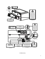
Page 17: ...PLS4 Back View 17...
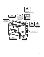
Page 18: ...PLS6 Front View 18...
Page 19: ......
Page 22: ...Chapter 3 Installation 22...
Page 40: ......
Page 48: ...Chapter 4 Operation 48...
Page 83: ...Chapter 5 Accessories 83...
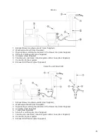
Page 99: ...Example Connection for PNP mode Example Connection for NPN mode 99...
Page 111: ...Chapter 6 Maintenance 111...
Page 119: ...www ulsinc com...

