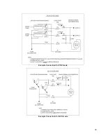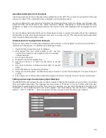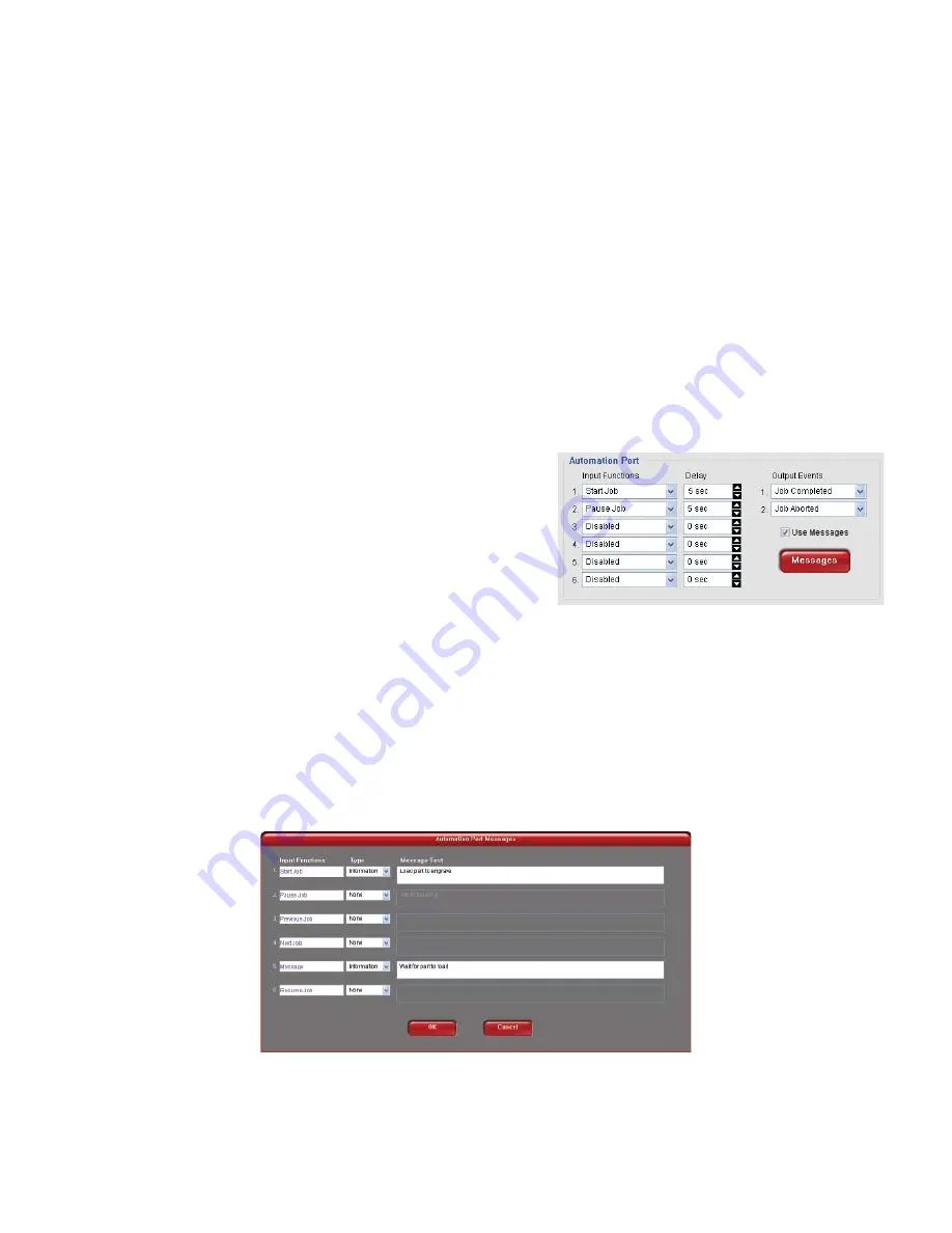
Available Automation Port Functions
Input and output events are configured in the systems tab of the UCP. The controls for automation Port setup
will only be visible if the automation board is plugged in and working properly.
You can configure the input functions to perform the following actions: Start Job, Pause Job, Resume Job,
Select Previous Job, Select Next Job, Initiate Autofocus, Display a Message, Z height and Quit the UCP
application. A delay can be programmed before each action occurs and messages can be assigned to each
action.
You can configure the Output Ports via the Output Events menu to supply information about the completion
and abortion of jobs. Jobs are aborted when any error or a pause occurs. The output ports will change state
when the event assigned to them occurs.
Automation Port Configuration Example
There are many ways to employ the automation port functions. In this example, we will use two functions --
“start job” and “pause job” -- to illustrate the Automation feature.
1. Verify that the Automation board is installed.
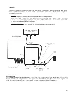
2. Wire signals from your control system to J2-1 and J2-2
and the return wires for each signal to J2-4 as indicated
in the schematics.
3. Print a job to the UCP.
4. Proceed to the UCP’s System Tab.
5. Set Input Function 1 to Start Job and add a 5 second
delay.
6. Set Input Function 2 to Pause Job and add a 5 second
delay.
7. Select Disabled for the remaining functions.
8. Using your control system, activate the signal to function 1 to start the selected job. The job should start
running.
9. Then using your control system, activate the signal to function 2 to pause the job. The job should pause.
Setting up messages to accompany input functions
The MESSAGE button allows the user to input a custom message that appears when a function is initiated
after a programmable delay. The message can also include a “Proceed” or “Cancel” button which the user
would have to select before the action took place. For example, you can add a message to the Start Job
command “Is the material loaded in the laser system?” and the message box can be set to display two
buttons -- “OK” or “CANCEL” -- which the user would have to press before the job can be initiated.
100
Summary of Contents for PLS4.75
Page 1: ...PLS User Guide PLS4 75 PLS6 75 PLS6 150D PLS6MW www ulsinc com Revision August 2012...
Page 5: ...Chapter 1 Specifications 5...
Page 8: ...Chapter 2 Safety 8...
Page 14: ...Tamper Proof Labels Safety Labels...
Page 15: ...ULS Fiber Laser Cartridge Labels 15...
Page 16: ......
Page 17: ...PLS4 Back View 17...
Page 18: ...PLS6 Front View 18...
Page 19: ......
Page 22: ...Chapter 3 Installation 22...
Page 40: ......
Page 48: ...Chapter 4 Operation 48...
Page 83: ...Chapter 5 Accessories 83...
Page 99: ...Example Connection for PNP mode Example Connection for NPN mode 99...
Page 111: ...Chapter 6 Maintenance 111...
Page 119: ...www ulsinc com...

