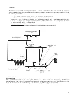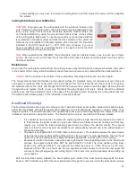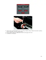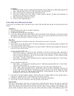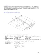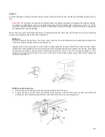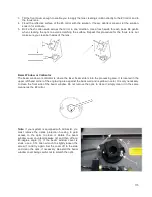
8. Power ON the laser system. If you are using the rotary for the first time or replaced the laser system’s
CPU, rotary calibration may be needed, so proceed to the next step. If rotary calibration is not needed
proceed to “Determining Graphic Placement.”
Rotary Calibration
1.
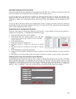
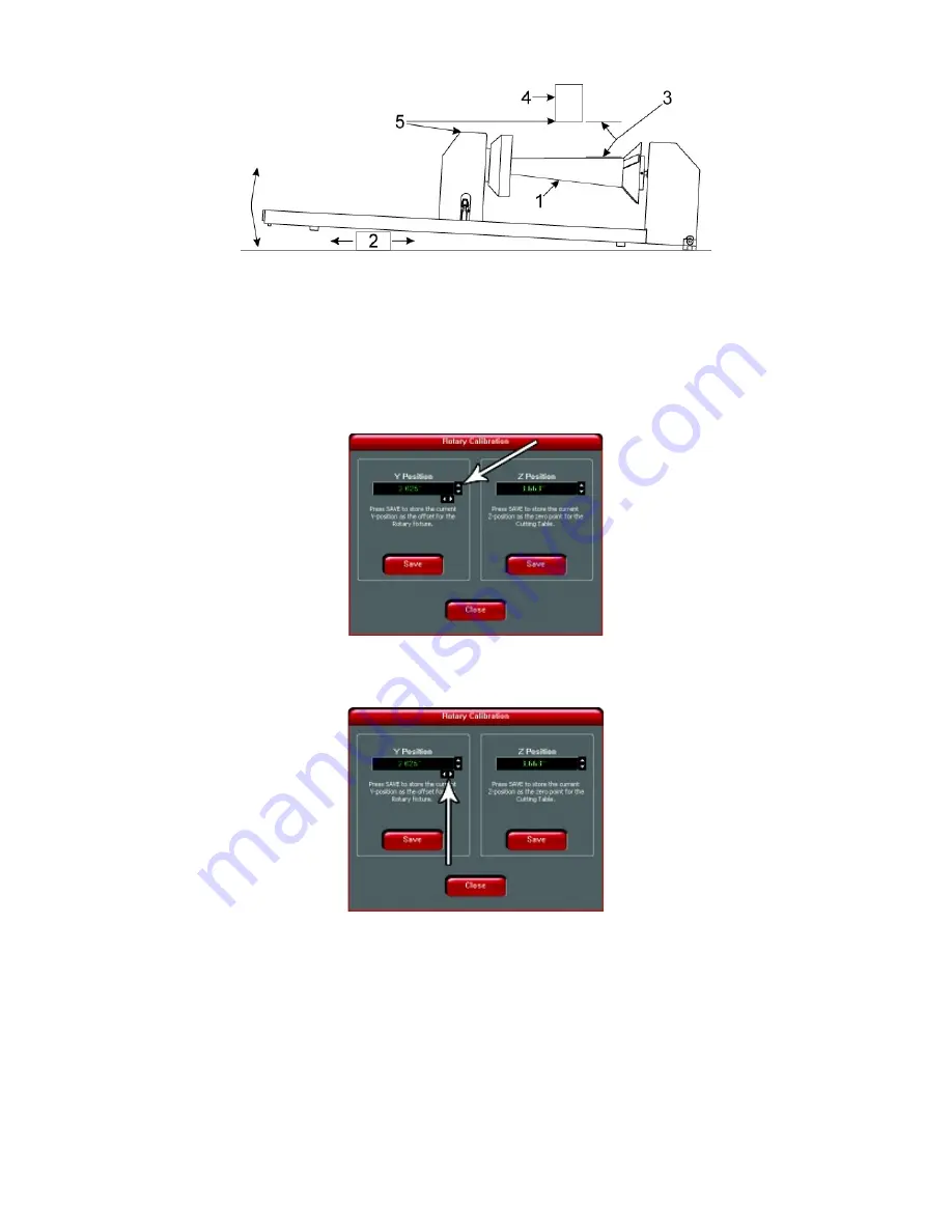
Select the System Tab of the UCP and press on the CALIBRATE button in the Rotary section.
2.
In the Y Position box, use the Y-Axis buttons shown to move the focus carriage so that the Y axis position
indicated is aligned with the rotational axis of the rotary fixture.
3.
Next, use the X-Axis buttons shown to move the focus carriage left or right and place the red dot pointer
over the flat part of the internal cone shaped fixture normally located on the left hand side of the rotary.
4.
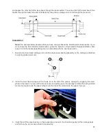
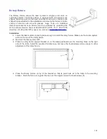
Now use the Z-Axis buttons in the rotary calibration dialog or the Z-Axis buttons on the machine keypad
to move the table up and down to focus using the Focus Tool on top of the flat surface of the internal cone
shaped fixture.
Note:
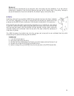
When calibrating the PLW6MW, the rotary fixture must be calibrated twice, once for each type of
laser source. Be sure to use a CO2 laser focus tool with a CO2 laser installed, and a fiber laser focus
tool with a fiber laser installed.
103
Summary of Contents for PLS4.75
Page 1: ...PLS User Guide PLS4 75 PLS6 75 PLS6 150D PLS6MW www ulsinc com Revision August 2012...
Page 5: ...Chapter 1 Specifications 5...
Page 8: ...Chapter 2 Safety 8...
Page 14: ...Tamper Proof Labels Safety Labels...
Page 15: ...ULS Fiber Laser Cartridge Labels 15...
Page 16: ......
Page 17: ...PLS4 Back View 17...
Page 18: ...PLS6 Front View 18...
Page 19: ......
Page 22: ...Chapter 3 Installation 22...
Page 40: ......
Page 48: ...Chapter 4 Operation 48...
Page 83: ...Chapter 5 Accessories 83...
Page 99: ...Example Connection for PNP mode Example Connection for NPN mode 99...
Page 111: ...Chapter 6 Maintenance 111...
Page 119: ...www ulsinc com...

