Determining Graphic Placement
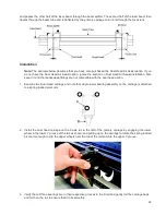
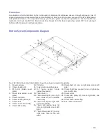
The next step is to align the graphics to be printed with the material inserted in the rotary fixture. Again, a wine
glass is used for illustration. You can use the X axis ruler or to be more precise use the Red alignment Laser
and the X-Y coordinate display in the UCP to position the graphics in the X axis.
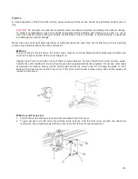
1. Using the Navigation buttons on the UPC, position the Focus Carriage above the material.
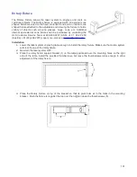
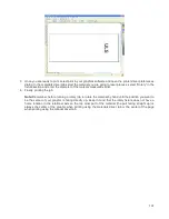
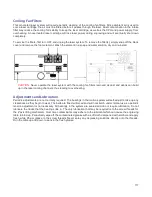
2. Move the carriage left or right until the center of the carriage or the red alignment laser is located where
you would like the top of the graphic to start on the material as indicated by the right most line in the
picture below. Make note of the X coordinate on the ruler or in the UCP.
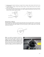
3. Now, position the center of the carriage or the red alignment laser is located where you would like the
graphic to end on the material as indicated by the left most line in the picture below. Make note of the X
coordinate on the ruler or in the UCP.
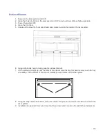
4. Finally rotate the material by hand until the position you want to be the center of your graphic is facing
directly up. Keep in mind that the rotary fixture does not have a home location in the rotational axis so the
top most part of the material (the part facing straight up) is always the center of the graphic when printing
using the materials driver tab or the center of the page when printing using the manual driver tab.
Printer Driver Settings (manual driver tab)
1. Start the graphic software you plan to print the job from and open or create the artwork you plan to print to
the laser system then open the print setup dialog in your graphic software, make sure your ULS laser
system printer driver is selected and open printer properties dialog.
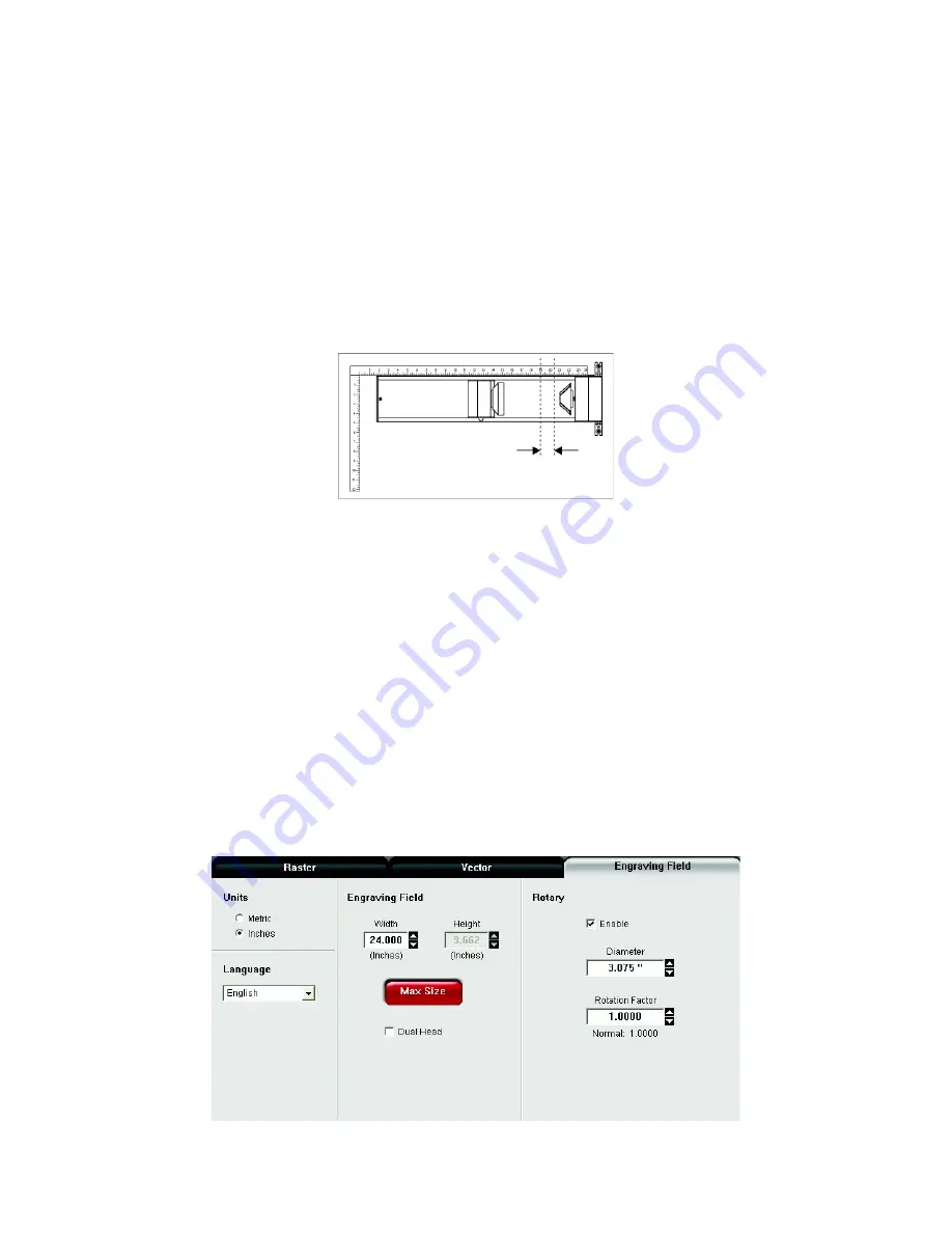
2. In the ULS printer driver properties dialog, press the Engraving Field sub-tab within the Manual Control
Tab.
3. Press the “Max Size” button to make sure the field is maximized before continuing.
4. Then select the “Enable” selection box in the Rotary section to enable rotary mode.
5. Type in the diameter of the material measured earlier.
6. Notice that while typing in the diameter, the height dimension of the engraving field changes
automatically. The new height value is equal to the circumference of the material. Make a note of this new
engraving field size.
105
Summary of Contents for PLS4.75
Page 1: ...PLS User Guide PLS4 75 PLS6 75 PLS6 150D PLS6MW www ulsinc com Revision August 2012...
Page 5: ...Chapter 1 Specifications 5...
Page 8: ...Chapter 2 Safety 8...
Page 14: ...Tamper Proof Labels Safety Labels...
Page 15: ...ULS Fiber Laser Cartridge Labels 15...
Page 16: ......
Page 17: ...PLS4 Back View 17...
Page 18: ...PLS6 Front View 18...
Page 19: ......
Page 22: ...Chapter 3 Installation 22...
Page 40: ......
Page 48: ...Chapter 4 Operation 48...
Page 83: ...Chapter 5 Accessories 83...
Page 99: ...Example Connection for PNP mode Example Connection for NPN mode 99...
Page 111: ...Chapter 6 Maintenance 111...
Page 119: ...www ulsinc com...

