background image

Overview

Accumulation of dirt and debris on the motion system components will cause uneven or rough engraving, loss of 
engraving position and premature failure. Accumulation of smoke or dirt on optics can result in loss of laser power 
and premature  failure.  It is important to keep your laser system as clean as possible to ensure trouble free 
operation and best results from laser processing. Always turn the laser engraving system OFF and unplug it 
before performing any cleaning procedures.

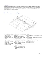
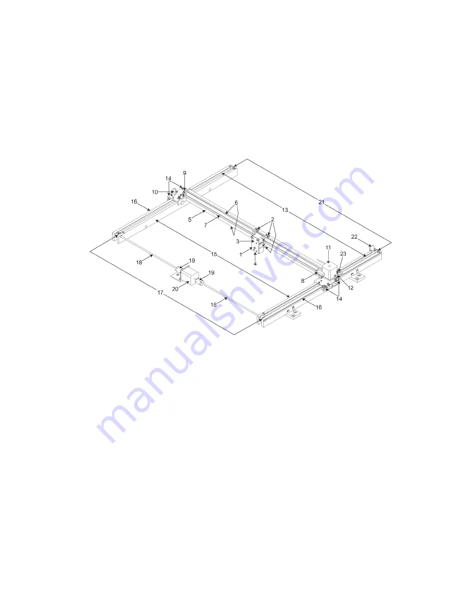
Motion System Components Diagram

Note: #2 Mirror Cover and X-Axis Motor Cover have been removed for visibility.

1.

Focus carriage

2.

X-Axis bearing (3)

3.

#3   mirror   (inside   cover 
plate)

4.

Focus lens (inside cover 
plate)

5.

X-Axis rail (arm)

6.

X-Axis bearing track (2)

7.

X-Axis belt

8.

X-Axis home sensor flag

9.

X-Axis idler pulley

10.

#2 mirror

11.

X-Axis motor and drive gear

12.

X-Y   home   sensor   board 
(upper flex board)

13.

Y-Axis belt (2)

14.

Y-Axis bearing (4) (2 on right 
side Y-Axis rail, 2 on left side 
Y-Axis rail)

15.

Y-Axis   rail   (2)(one   right   side 
and one left side)

16.

Y-Axis   rail   bearing   track   (2) 
(one on right side, one on left 
side)

17.

Y-Axis drive gear (2) (one on 
right   side,   one   on   the   left 
side)

18.

Y-Axis shaft (2) (one on right side, one on left 
side)

19.

Y-Axis shaft  flex coupler  (one  on right  side, 
one on left side)

20.

Y-Axis motor

21.

Y-Axis idler pulley (2) (one on right side, one 
on left side)

22.

Y-Axis home sensor flag

23.

Flex cable (not shown)

112

Summary of Contents for PLS4.75

Page 1: ...PLS User Guide PLS4 75 PLS6 75 PLS6 150D PLS6MW www ulsinc com Revision August 2012...

Page 2: ...Universal Laser Systems Inc All other company and product names are trademarks or registered trademarks of their respective companies Universal s laser systems are protected under one or more of U S P...

Page 3: ...988 Universal Laser Systems has been committed to continually improving our technology and customer driven laser solutions Your satisfaction is very important to us and we welcome your feedback Tell u...

Page 4: ...nce Guide contains the Software Installation CD Please follow the instructions for proper installation Warranty Your Reference Guide contains Warranty documents pertaining to your purchase Should you...

Page 5: ...Chapter 1 Specifications 5...

Page 6: ...System High pressure vacuum blower capable of 250 CFM cubic feet per minute 6 inches static pressure 425m3 hr at 1 5kPa 500 CFM cubic feet per minute 6 inches static pressure 850m3 hr at 1 5kPa Compu...

Page 7: ...Lasers 10 25 30 40 50 60 and 75 watts Fiber Laser 30 watts 10 25 30 40 50 60 and 75 watts equipped for two lasers Power Consumption up to 110V 10A 240V 5 230V 15A Overall Dimensions WxHxD 36 x 39 x 36...

Page 8: ...Chapter 2 Safety 8...

Page 9: ...re extinguisher should be kept on hand at all times NEVER LEAVE MATERIALS IN THE LASER SYSTEM AFTER LASER PROCESSING HAS FINISHED Always remove all material including scrap material from the machine a...

Page 10: ...trum For your protection the laser is contained within a Class 1 enclosure designed to completely contain the CO2 laser beam CAUTION Use of controls or adjustments or performance of procedures other t...

Page 11: ...intense light that appears during the engraving or cutting process is the product of material combustion or vaporization DO NOT STARE AT THIS INTENSE LIGHT FOR LONG PERIODS OF TIME OR VIEW DIRECTLY W...

Page 12: ...on Emission Warning Device A visible warning light that indicates when the laser is capable of emitting laser radiation 4 Attenuator A mechanical device to block emission of laser radiation This devic...

Page 13: ...special eyewear and clothing and regular inspection of all safety measures surrounding the controlled area in which a Class 4 laser system is operated The LSO may be required to maintain records as ne...

Page 14: ...Tamper Proof Labels Safety Labels...

Page 15: ...ULS Fiber Laser Cartridge Labels 15...

Page 16: ......

Page 17: ...PLS4 Back View 17...

Page 18: ...PLS6 Front View 18...

Page 19: ......

Page 20: ...ective 2002 96 ECC WEEE Directive based on the standards listed Standards Used Safety EN 60950 2002 EN 60825 1 2007 Class 2 EMC EN 55024 1998 Class A EN 55022 2003 Class A EN 61000 3 2 2001 class A EN...

Page 21: ...ions Operation of this equipment in a residential area is likely to cause harmful interference in which case the user will be required to correct the interference at his or her own expense Users shoul...

Page 22: ...Chapter 3 Installation 22...

Page 23: ...sent in a confined unventilated room can create a health hazard 4 For best results since the laser cartridges are air cooled we recommend operating the laser system between the ambient temperatures of...

Page 24: ...l an exhaust gate to adjust airflow and to close off the exhaust when the laser is not in use Place this gate near the laser system within 5 to 10 feet 1 50 to 3 00 meters 6 Use a short piece of indus...

Page 25: ...ser Supplied 7 Connection to laser system 8 Exhaust On Off switch User Supplied PLS6 75 and PLS6 150D 1 Exhaust blower mounted outside User Supplied 2 Weatherproof shield User Supplied 3 Rigid ducting...

Page 26: ...dows 7 2 GB of RAM minimum 40 GB hard drive 15 GB free space minimum VGA monitor minimum 1024 x 768 resolution CD DVD Drive Mouse and keyboard Available USB 2 0 Hi Speed compliant port only Computer s...

Page 27: ...settings can be controlled through the power options in the Windows control panel on your PC The illustrations below show you how to disable power management XP Vista and 7 For the Power Scheme in use...

Page 28: ...you are installing software Note If the setup window does not automatically launch you can launch it manually Locate your CD or DVD drive using Windows Explorer and launch the Setup exe application to...

Page 29: ...sible into each cart leg 1 Back panel 2 Legs both are identical 3 Side panels two 4 Shelf panel 5 1 4 20 x socket head screws w lock flat washers four 6 Nuts four 7 Locking casters four are identical...

Page 30: ...gh narrow doorways to install in its intended location the system can be detached from the cart and transported in two pieces If so follow the steps below if not skip laser cartridge installation a In...

Page 31: ...sconnected in step b reside Gently pull the cables up and rest them on top of the sheet metal as shown below e Close and latch the rear cover f Tape the front and top doors closed using strong shippin...

Page 32: ...n on a dolly for transport i The cart and laser system can now be moved separately to the install location j Reassemble in reverse order by placing the cart into position first and locking the casters...

Page 33: ...cks so make sure the latches are unlocked Note Access latches for the laser cover are lockable If you lose your keys please contact our Customer Service Team at 480 609 0297 USA 43 1 402 22 50 Austria...

Page 34: ...the laser cartridge in the top position 5 Important Higher powered CO2 lasers can weigh up to 29 pounds Use caution when installing a cartridge Pick up the laser cartridge by the ends and tilt it at...

Page 35: ...thly check for obstructions such as pinched wires or hoses or a binding laser latch Once installed verify that the alignment plate is centered within the alignment fork 7 Plug in each power connector...

Page 36: ...the laser cover are lockable If you lose your keys please contact our Customer Service Team at 480 609 0297 USA 43 1 402 22 50 Austria 81 45 224 2270 Japan or e mail us at support ulsinc com for new k...

Page 37: ...t plate contacts the inside edge of the tall block of the alignment fork 5 Slowly rotate the laser cartridge down into place making sure that the alignment plate is centered in the groove in the align...

Page 38: ...g in the power connector to the laser cartridge 7 Gently close the rear cover making sure not to pinch any wires or hoses 8 Once the laser cartridges have been installed proceed to Laser System Leveli...

Page 39: ...the front 2 and rear cart legs 3 Adjust the caster height using the adjustment nut 4 until both the rear and front of the cart are level with respect to each other Once the system is level secure all...

Page 40: ......

Page 41: ...at the correct height tighten the lock nut 1 When you are done the focus tool fit at all four corners should be the same Alternate leveling method For the best leveling results use a digital caliper...

Page 42: ...ery holder drawer on the side of the laser system Install the provided 9 volt Thermal Sensor battery using a flat head screw driver to open the drawer Note A properly installed 9 volt battery is neces...

Page 43: ...t this time Then select Next to continue a Select Install the software automatically Then Select Next to continue You do not need to insert the Software Installation CD ROM b Select Finish to close th...

Page 44: ...ystem 5 With the top door open a red dot will appear on the masking tape 3 The red dot should appear centered within 1 8 inch 3 mm If not turn off the laser system remove and re install the laser cart...

Page 45: ...t ulsinc com Note For this example we will be using CorelDRAW and the CorelDRAW sample file provided on the installation CD The file is also provided in eps or dxf for use in other applications if Cor...

Page 46: ...sired material Aluminum Anodized Figure 5 4 Set the Fixture Type to NONE Note If you were using an optional accessory or custom fixture you would choose it from the fixture list 5 Measure the thicknes...

Page 47: ...cessary If you cannot resolve the issue please contact your distributor or the ULS Customer Service Department Never leave the laser system unattended while laser processing Step 5 Material Removal an...

Page 48: ...Chapter 4 Operation 48...

Page 49: ...into a material by etching a pattern of dots into the material at high resolutions up to 1000 dpi and a vector mode in which the laser follows a two dimensional path to cut or mark a shape into a mat...

Page 50: ...ser system is able to print shaded images and photographs If you desire a solid background removal for certain elements of your graphic instead of a dither pattern you must make those elements solid b...

Page 51: ...nly one of the lasers for an application by deselecting the top or bottom laser If both lasers are selected the materials database will calculate the laser settings based on the combined power of both...

Page 52: ...llows you to treat multipage documents in different ways By default multipage documents are treated as separate jobs with each page having to be selected in the UCP and run individually This setting a...

Page 53: ...record that you can fill in Right clicking on an existing material and selecting clone allows you to make a copy of an existing material and then edit it Creating or editing materials records requires...

Page 54: ...g Blue Pen In this section of the Material Editor window you enter the laser job settings to be used for vector marking These settings must be determined for your material through testing For a deeper...

Page 55: ...abort these changes by selecting Cancel selecting OK or APPLY will approve the changes Save Button The save button brings up a dialog box which allows you to save a snapshot of the laser job settings...

Page 56: ...ined below Color table The color table contains a list of all of the job settings that are tied to colors in the graphic being printed To change job settings for color select that color so it is highl...

Page 57: ...00 PPI and image densities 6 and 7 fix pulses at 1000 PPI Waveform Fiber only Changing the waveform setting for the fiber laser source will allow you to achieve many different types of effects on your...

Page 58: ...e permanently saved until the OK or APPLY buttons are pressed Apply Button The APPLY button saves all changes made to the printer driver settings Default Button The Default button will reset the drive...

Page 59: ...get the desired results By default all other colors are forced to raster mode and are not used since colored raster data is converted to grayscale The red pen is left in rast vect mode and it is recom...

Page 60: ...de and it is recommended that all vector cut lines in the graphic being printed be colored red so that they will be interpreted as vectors Any black vector lines will the converted to raster objects R...

Page 61: ...and the black color job settings are used for processing Because of this you will notice that the color table is reduced to one color black when this mode is selected The dither pattern applied is th...

Page 62: ...s Higher image densities will produce finer vector detail but may reduce productivity and vice versa for lower image densities By running samples on scrap materials and tying different density setting...

Page 63: ...created will vary with density chosen Higher density settings such as 5 will produce a more densely packed finer pattern and lower resolution settings such as 2 will produce a loosely packed coarser...

Page 64: ...r Setting The Tuning Value An easy way to set the tuning value on a given material at a desired processing speed is to create a graphic consisting of about 20 thin vertical lines about 1 25 4 mm tall...

Page 65: ...g at high speeds Having too much CONTRAST will cause the affected areas to appear too thick bold or over powered Definition DEFINITION increases laser power at the edges of thin graphical elements in...

Page 66: ...d upper case letters as in the following example This is a test to set contrast definition and density for High Speed Engraving Engrave the sample text with the settings established in step 1 on a scr...

Page 67: ...ted in the color table but all vectors of a given color will be grouped and executed based on which of the following controls is selected None This selection does no sorting or enhancing and prints in...

Page 68: ...fect the engraving field page size and other miscellaneous settings The controls in the sub tab are described below Units Units allows you to change units used between Metric and English Language Sele...

Page 69: ...all models Please contact Universal Laser System for more details Diameter If a rotary fixture is installed in your laser system the diameter of the cylindrical object being processed is entered in th...

Page 70: ...laser system are duplicated here The green START button begins processing the selected job The PAUSE button stops the engraving process Pressing the PAUSE button again resumes the engraving process w...

Page 71: ...preview screen 3 Using the X Y manual motion buttons you can move the focus carriage to a location on the processing table in the laser system using the red pointer diode as reference then select an a...

Page 72: ...laser system Navigation Arrows on either side of the currently selected print job number allow you to navigate through the print jobs stored on your hard drive The folder button displays a pop up win...

Page 73: ...ignment Mode window for checking and adjusting alignment of the laser to the motion system The Alignment feature should only be used if instructed by the Customer Service Team at ULS CUTTING TABLE all...

Page 74: ...d in the laser system as well as status information about those devices LASER displays information about the current laser cartridge s installed in the laser system If a red x appears this indicates t...

Page 75: ...n system was paused If the Start button is pressed while the machine is in a paused state it will restart processing at the beginning of the laser job SELECT This button activates the currently highli...

Page 76: ...te If you want to change a laser setting for a particular color in the selected job move the cursor to row C D or E using the UP DOWN navigation buttons and then use the RIGHT LEFT navigation buttons...

Page 77: ...the cutting table use of this accessory is described in the accessories section of the manual Caution Material to be laser processed must fit completely within the machine so that the all access doors...

Page 78: ...axis position reads zero and use the manual focus tool as described in the manual focus section above to verify that the surface of the engraving table is at the focus plane For the PLS6MW make sure...

Page 79: ...ibrated to the lens being used To verify this move the Z axis manually until the Z axis position reads zero and use the manual focus tool as described in the manual focus section above to verify that...

Page 80: ...eld If you are using the manual printer driver tab the page size in your graphic software may also be reduced to match the size of your material but remember to adjust the page size in the printer dri...

Page 81: ...for laser processing using variable spacing between the dots to create the illusion of shades of gray These dither patterns are relatively coarse so it is not necessary to use high resolution bitmaps...

Page 82: ...ystem is a 2D device so you must create a 2D drawing view of the object you want to laser process You cannot print 3D parts and assemblies directly to the laser system To control placement of your job...

Page 83: ...Chapter 5 Accessories 83...

Page 84: ...e filtered CAUTION A contaminated air supply can cause damage to the laser system Air or gas supply pressures higher than 60 PSI 4 1 bar can rupture the internal hoses Damage to the laser system from...

Page 85: ...endent on the application The backsweep fitting is geared more toward engraving applications and the cone is geared more toward cutting applications CAUTION Do not use flammable or corrosive gases as...

Page 86: ...has built in pressure sensors that will detect insufficient supply pressure and will stop laser processing An error message The air pressure is low or unstable will appear on the computer monitor indi...

Page 87: ...en the laser system is powered on and the top door is open Note If you remove the backsweep always remember to reattach the mounting thumbscrew 1 to seal the air feed port Air Assist Cone To install t...

Page 88: ...ULS Computer Controlled Compressed Air Unit The ULS Computer Controlled Compressed Air Unit provides a 50 PSI max pressure and 2 0 cfm free air flow 3 2 bar and 3 2 cubic meters hour source of clean d...

Page 89: ...FF light is illuminated the compressor should be off and no compressed air is being supplied Manual ON OFF switch turns compressor on or off manually to verify operation Maintenance The particle filte...

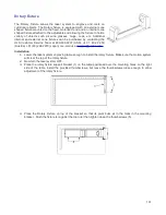
Page 90: ...d carefully insert the cutting table into the laser system so that the four feet on the bottom of the cutting table are resting on the engraving table in the laser system Then slide the table back and...

Page 91: ...alled slightly loose and then adjusted to match the edges of the processing area by placing the cutting table back into the machine and following step 7 of the installation instructions above Dual Hea...

Page 92: ...gs are not compatible with the dual head option 1 Examine the Dual Head carriage and note that single lower bearing assembly on the carriage is attached to a spring loaded pivot arm 2 Install the dual...

Page 93: ...unting screws as shown below Installation is now complete unless you have the Dual Head Air Assist Option in which case you can proceed to optional steps below Dual Head Air Assist Installation a If y...

Page 94: ...ge will appear asking you to verify your page size in your graphics software because the driver s page Width will now be half of what it was Make a note of the new dual head page size 4 Adjust the pag...

Page 95: ...density depending on your material you can engrave smaller text produce sharper graphics and photographs and vector mark and cut thinner lines with the same laser power With the HPDFO it is also poss...

Page 96: ...ive to flatness of material and accuracy of focus but with the trade off of a larger spot size Contact Universal Laser Systems customer support for help in choosing the right lens for your application...

Page 97: ...J9 connector at top of Automation Kit 4 Optional If you are using an ULS computer Controlled Compressed Air Unit for air assisted laser processing use the included RJ9 to RJ9 cable to connect the comp...

Page 98: ...ister Automation Kit I O Connections The automation kit connector J6 is used to poll the two programmable status outputs It can be used in two modes selectable by the PNP NPN switch on the top of the...

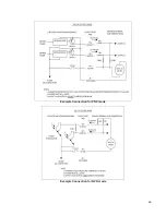
Page 99: ...Example Connection for PNP mode Example Connection for NPN mode 99...

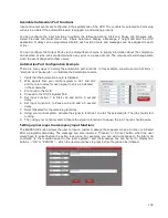
Page 100: ...eature 1 Verify that the Automation board is installed 2 Wire signals from your control system to J2 1 and J2 2 and the return wires for each signal to J2 4 as indicated in the schematics 3 Print a jo...

Page 101: ...2 50 Austria 81 45 224 2270 Japan or e mail us at support ulsinc com Installation 1 Lower the laser system engraving table enough to install the rotary fixture Make sure the motion system will clear t...

Page 102: ...m of the material Lower the lever on the end of the fixture to lock the material in place The rubber pads should keep the material from slipping Note If the material does not have an open end you can...

Page 103: ...xis of the rotary fixture 3 Next use the X Axis buttons shown to move the focus carriage left or right and place the red dot pointer over the flat part of the internal cone shaped fixture normally loc...

Page 104: ...E buttons on the Rotary Calibration dialog If asked to overwrite an existing position accept the new value by pressing YES 6 Once complete press the CLOSE button and the focus carriage will re home 7...

Page 105: ...the center of your graphic is facing directly up Keep in mind that the rotary fixture does not have a home location in the rotational axis so the top most part of the material the part facing straigh...

Page 106: ...12 Then set the appropriate power and speed settings before printing the job Note Remember before running a rotary job to rotate the material by hand until the position you want to be the center of yo...

Page 107: ...Finally printing the job Note Remember before running a rotary job to rotate the material by hand until the position you want to be the center of your graphic is facing directly up Keep in mind that...

Page 108: ...being used and image being printed For example large text engraved on wood is much less sensitive than small text engraved on anodized aluminum For optimal results on sensitive materials such as acryl...

Page 109: ...regardless of vector color or thickness All vectors which are not blue in color will be converted to red cut vectors when the materials database is used If the manual tab of Laser Interface is used d...

Page 110: ...he all strokes as vectors option with the manual controls all vectors will be imported as vectors regardless of line width and will use the laser settings mapped from the color table PDF import proces...

Page 111: ...Chapter 6 Maintenance 111...

Page 112: ...cus carriage 2 X Axis bearing 3 3 3 mirror inside cover plate 4 Focus lens inside cover plate 5 X Axis rail arm 6 X Axis bearing track 2 7 X Axis belt 8 X Axis home sensor flag 9 X Axis idler pulley 1...

Page 113: ...ays dampen your paper towel or cloth with the cleaning solution outside of the laser system and then wipe down the parts you are cleaning with the dampened cloth Clean X rail and Y rail by using eithe...

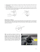
Page 114: ...irror the mirror cover must be removed Remove the thumbscrew and slide the cover to the right and then lift the cover straight up Inspect the 2 mirror and clean it only if there is debris present To c...

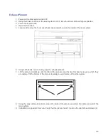
Page 115: ...the laser beam enters into the processing area It is located in the upper left hand corner of the engraving area against the back wall and is yellow in color It is only necessary to clean the front si...

Page 116: ...system 6 Using both hands reach in and grasp the exhaust plenum 7 Lift the plenum straight up until the tabs of the plenum clear the two flat head screws on which they are resting Tilt the bottom of t...

Page 117: ...moved as dust and debris can build up in the laser cooling channels thus leading to overheating Adjustments and Lubrication Periodic adjustments are not normally required The bearings in the motion sy...

Page 118: ...ebris Clean ONLY if dirty Every month Clean cooling fan filters Clean Z Axis lead screws with white lithium grease Check for X Axis and Y Axis belt wear Replace as necessary Check and or clean X Axis...

Page 119: ...www ulsinc com...

Reviews: