Step 3: Assembling and Connecting Your Laser System
Familiarize yourself with the instructions before getting started.
The final step in installation is to assemble your laser system, install the laser cartridge(s), level the laser system,
make final connections and perform a beam alignment check. Do not power up your laser system until the final
step, “Checking Beam Alignment.”
CAUTION:
Do not attempt to move or lift this laser system alone. Obtain assistance from additional people
when lifting or carrying the laser system and make sure to secure the motion system and doors before lifting.
Injury may occur if improper lifting techniques are used or the system is dropped.
Machine Assembly
1. Unpack the laser system.
2. Remove the unassembled cart from the top of the laser system.
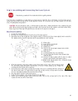
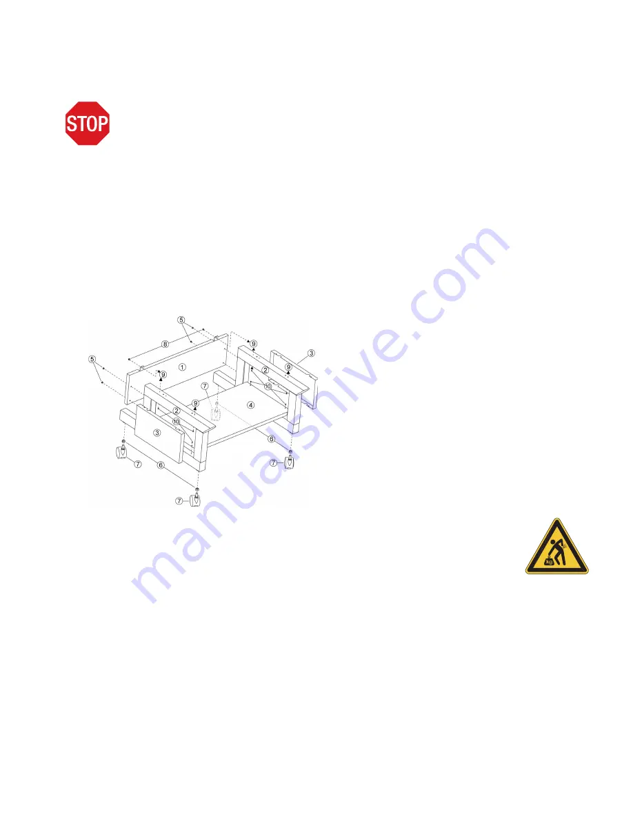
3. Assemble the cart as it appears in the diagram below, but leave all of the screws slightly loose, except for
the casters which should be tightened as far as possible into each cart leg.
(1) Back panel
(2) Legs (both are identical)
(3) Side panels (two)
(4) Shelf panel
(5) 1/4-20 x ½ socket head screws w/lock & flat
washers (four)
(6) Nuts (four)
(7) Locking casters (four are identical)
(8) 10-32 x 3/8 socket head screws w/lock & flat
washers (two)
(9) Connect to laser system with 1/4-20 x ½ socket
head screws w/lock & flat washers (four)
(10)Attach side panels with 8-32 x 3/8 button head
cap screws (eight)
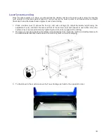
4. With the assistance of another person, place the system on top of the cart and loosely install
the provided screws that attach the machine to the cart. These screws go up through the
cart legs into the bottom of the machine.
5. Open front door all the way to ensure that it does not rub on or interfere with the cart legs. If
the door should come in contact with the cart legs, gently pull the cart legs apart to ensure
there is noncontact between the door and the cart legs.
6. Securely tighten all the screws at this point.
7. Place the laser system in the desired location for operation.
8. Attach your exhaust system’s wire-reinforced rubber hose to the exhaust port at the rear of the laser
system and secure with a hose clamp.
29
Summary of Contents for PLS4.75
Page 1: ...PLS User Guide PLS4 75 PLS6 75 PLS6 150D PLS6MW www ulsinc com Revision August 2012...
Page 5: ...Chapter 1 Specifications 5...
Page 8: ...Chapter 2 Safety 8...
Page 14: ...Tamper Proof Labels Safety Labels...
Page 15: ...ULS Fiber Laser Cartridge Labels 15...
Page 16: ......
Page 17: ...PLS4 Back View 17...
Page 18: ...PLS6 Front View 18...
Page 19: ......
Page 22: ...Chapter 3 Installation 22...
Page 40: ......
Page 48: ...Chapter 4 Operation 48...
Page 83: ...Chapter 5 Accessories 83...
Page 99: ...Example Connection for PNP mode Example Connection for NPN mode 99...
Page 111: ...Chapter 6 Maintenance 111...
Page 119: ...www ulsinc com...

