35
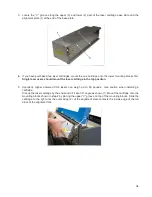
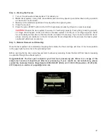
6. Slowly rotate the laser cartridge down into place, making sure that the alignment plate is centered in the
groove in the alignment fork. The laser should click onto the spring loaded laser catch shown in step 2 to
lock it in place. Never force the laser onto the laser latch. If the laser does not install smoothly, check for
obstructions such as pinched wires or hoses or a binding laser latch. Once installed, verify that the
alignment plate is centered within the alignment fork.
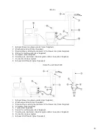
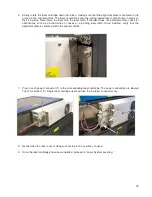
7. Plug in each power connector (1) to the corresponding laser cartridge. The power connectors are labeled
Top (2) or Bottom (3). Single laser cartridge users will use the top laser connector only.
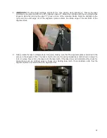
8. Gently close the rear cover, making sure not to pinch any wires or hoses.
9. Once the laser cartridges have been installed, proceed to “Laser System Leveling.”
Summary of Contents for PLS4.75
Page 1: ...PLS User Guide PLS4 75 PLS6 75 PLS6 150D PLS6MW www ulsinc com Revision August 2012...
Page 5: ...Chapter 1 Specifications 5...
Page 8: ...Chapter 2 Safety 8...
Page 14: ...Tamper Proof Labels Safety Labels...
Page 15: ...ULS Fiber Laser Cartridge Labels 15...
Page 16: ......
Page 17: ...PLS4 Back View 17...
Page 18: ...PLS6 Front View 18...
Page 19: ......
Page 22: ...Chapter 3 Installation 22...
Page 40: ......
Page 48: ...Chapter 4 Operation 48...
Page 83: ...Chapter 5 Accessories 83...
Page 99: ...Example Connection for PNP mode Example Connection for NPN mode 99...
Page 111: ...Chapter 6 Maintenance 111...
Page 119: ...www ulsinc com...


