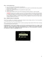
Step 4 – Starting the Process
1. Turn on the exhaust and laser system if not already on.
2.
Note:
Laser system cooling fans are variable speed and may speed up and slow down during operation
as needed to cool the lasers.
3. Make sure the material is positioned correctly within the engraving area.
4. Close the top door.
5. Press the green START button on the UCP to begin laser processing (Figure 6 on previous page).
CAUTION:
Observe the laser system to ensure it is functioning properly. If everything is working properly,
an image should appear on the test card as the laser system runs the job. If no image appears, check
focus manually as described in the User Guide and adjust if necessary. If you cannot resolve the issue,
please contact your distributor or the ULS Customer Service Department. Never leave the laser system
unattended while laser processing.
Step 5 – Material Removal and Reloading
Once the laser system has completed processing the material, the focus carriage will move to the home position
in the upper right hand corner of the processing field.
Before opening the top door, wait a few seconds to allow any remaining fumes that are left from laser processing
to evacuate through the exhaust system.
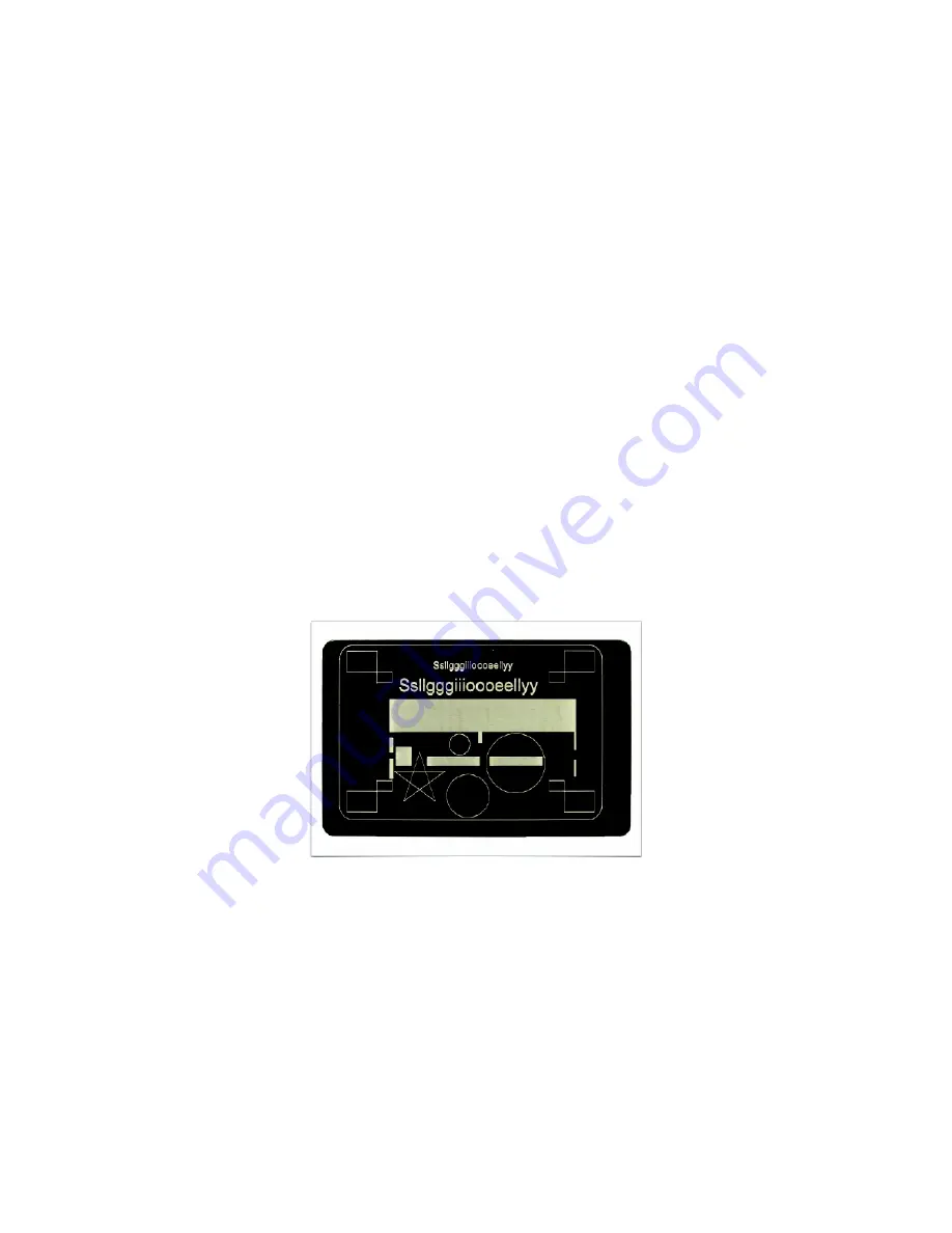
Congratulations! You have just completed your first laser processing job. Below is an image of the
sample test card as it should look after laser processing. If your results are not satisfactory, please
contact the Customer Service Department at 480-609-0297 (USA), +43 1 402 22 50 (Austria), +81 (45) 224-
2270 (Japan) or e-mail us at support@ulsinc.com.
47
Summary of Contents for PLS4.75
Page 1: ...PLS User Guide PLS4 75 PLS6 75 PLS6 150D PLS6MW www ulsinc com Revision August 2012...
Page 5: ...Chapter 1 Specifications 5...
Page 8: ...Chapter 2 Safety 8...
Page 14: ...Tamper Proof Labels Safety Labels...
Page 15: ...ULS Fiber Laser Cartridge Labels 15...
Page 16: ......
Page 17: ...PLS4 Back View 17...
Page 18: ...PLS6 Front View 18...
Page 19: ......
Page 22: ...Chapter 3 Installation 22...
Page 40: ......
Page 48: ...Chapter 4 Operation 48...
Page 83: ...Chapter 5 Accessories 83...
Page 99: ...Example Connection for PNP mode Example Connection for NPN mode 99...
Page 111: ...Chapter 6 Maintenance 111...
Page 119: ...www ulsinc com...


