The Printer Driver Interface
The printer driver is a piece of software that allows you to create jobs for the laser system using the Windows print
system. The printer driver has a preferences dialog with two tabs which allow you to set various parameters for a
print job. One tab offers a materials-based approach to setting job parameters and the other offers a more
detailed manual approach to setting job parameters.
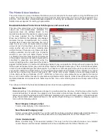
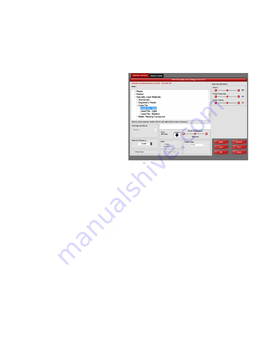
Materials Database Printer Driver Tab (beginner and casual user)
This tab of the printer driver is for beginners and
casual user and automatically calculates the
appropriate laser job settings based on the
material selected and the maximum output power
of the laser installed. For the PLS6MW Multi-
Wave Laser Platform, the database only displays
materials that are compatible with the currently
installed laser. Please note that when this tab is
used to set up a job, all raster data is printed
using one set of job settings, all vector cut data
using another set and all vector marking data
using a third set. There are only three sets of job
settings available, one for each type of graphic
element in your print job: raster objects, vector
cut objects and vector mark objects. All elements
of the graphic interpreted as raster objects will be
converted to grayscale and printed using the
raster job settings with a grayscale dither pattern
applied. A dither pattern is a method of mimicking shades of gray using patterns of dots with varying spacing. Dots
further apart will appear lighter gray and dots closer together will appear darker gray. This is how the laser system
is able to print shaded images and photographs. If you desire a solid background removal for certain elements of
your graphic instead of a dither pattern, you must make those elements solid black in color. Objects to be vector
cut must be in red and must have a thickness of .001” (.0254 mm) or less. Objects to be vector marked must be
in blue and must have a thickness of .001” (.0254 mm) or less. Any vector elements in your graphic that are not
blue or red in color will be converted to grayscale and printed as raster objects. Order of execution when using the
materials database tab proceeds with raster objects first, then vector marking objects and finally vector cutting
objects.
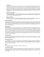
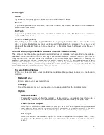
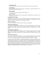
The various controls in the materials database printer driver tab are explained below:
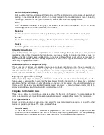
Materials Tree
Materials settings in the database are arranged in a multi-leveled tree structure. Click the plus symbol next to
a material category to expand the category, and then select a material type. Double clicking on a material
allows you to read the material record for standard materials and to read and edit custom or cloned materials
using the materials editor explained laser in this section. Right clicking on a material or category opens a
menu with the following options.
New Category (category only)
Create a new category in the materials tree
New Material (Category only)
Create a new custom material. You can then edit the settings using the material editor described later in
this section. Please note that new materials will not be compatible with the VLS air filtration unit.
Clone (material only)
Make a custom copy of the selected material. This copy can then be edited to make a new material
record. Please note that cloned materials will not be compatible with the VLS air filtration unit.
50
Summary of Contents for PLS4.75
Page 1: ...PLS User Guide PLS4 75 PLS6 75 PLS6 150D PLS6MW www ulsinc com Revision August 2012...
Page 5: ...Chapter 1 Specifications 5...
Page 8: ...Chapter 2 Safety 8...
Page 14: ...Tamper Proof Labels Safety Labels...
Page 15: ...ULS Fiber Laser Cartridge Labels 15...
Page 16: ......
Page 17: ...PLS4 Back View 17...
Page 18: ...PLS6 Front View 18...
Page 19: ......
Page 22: ...Chapter 3 Installation 22...
Page 40: ......
Page 48: ...Chapter 4 Operation 48...
Page 83: ...Chapter 5 Accessories 83...
Page 99: ...Example Connection for PNP mode Example Connection for NPN mode 99...
Page 111: ...Chapter 6 Maintenance 111...
Page 119: ...www ulsinc com...


