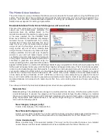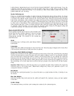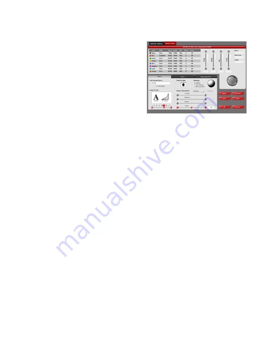
Manual Printer Driver Interface Tab (advanced users)
This tab of the printer driver is for the advanced user and
allows the user to manually configure all laser job settings.
This approach allows the user much more configurability, but
requires a deeper knowledge of the laser job settings and
how they affect laser processing. Please note that when this
tab is used laser settings are applied to the graphic being
printed by color and each color can contain raster and vector
data. There are eight colors available to which you can
assign laser power and processing speed setting. Elements
in the graphic are interpreted as vectors only if their line
thickness is .001 (.0254 mm) or less. All other elements in
the graphic will be treated as raster objects. Laser power
and processing speed settings are displayed based on the
wavelength of your installed laser. Different values for these
settings can be assigned to raster and vector objects by
color. Any objects which have a color that does not map directly into a color in the driver table will be matched to
the nearest color. Any multicolor objects, such as grayscale or color bitmaps, will have a black and white dither
pattern applied and will be mapped to the black power and speed settings. Order of execution when using the
manual driver tab proceeds down the color table from top to bottom with all raster objects being completed first,
then vector objects follow.
A useful feature of the dual materials and manual tabs is the ability to select a material in the materials driver and
then switch over to the manual tab. When you do this the settings stored in the materials database for the material
selected will be transferred to the manual tab, including the laser power and processing speeds for rasters and
vectors which will transfer to the black, red and blue colors in the color table.
The various controls in the Manual Printer Driver Interface Tab are explained below:
Color table
The color table contains a list of all of the job settings that are tied to colors in the graphic being printed. To
change job settings for color, select that color so it is highlighted, then use the controls to the right of the color
table to change the desired settings. It is possible to highlight more than one color at a time and the changes
will be applied to all the highlighted colors.
Color Order (Order of Execution)
You can change the order of the colors in the color table by dragging the color up or down the list in the
table. This will change the order of execution of objects in those colors. You can only change color order
when first printing a job. After printing the job to the UCP the color order becomes fixed for that job.
% Power
The Power setting allows you to select the laser power level to be applied from 0 to 100%. This setting is
directly related to how deep the cutting or engraving will be. The higher the setting, the deeper it engraves
or cuts, and vice-versa. Power essentially determines the duty cycle of each laser pulse in the job. Laser
pulse frequency is controlled by the PPI setting for vectors and by the image density selected for rasters
(image densities 5 and below fix pulses at 500 PPI and image densities 6 and 7 fix pulses at 1000 PPI).
% Speed
This setting allows you to select processing speed from 0 to 100%. This setting determines the maximum
rate of travel of the motion system. Actual engraving time (throughput) is not only dependent on the %
Speed setting, but is also dependent on the size, intricacy and the placement of the graphic in the
engraving field. The motion system will accelerate/decelerate at a fixed rate up to the chosen speed. If the
motion system cannot achieve the chosen speed based on the size and intricacy of the graphic or
graphical placement in the field, it will automatically adjust its speed to the maximum speed it can
achieve. This is evident when you see the motion system automatically slow down while cutting curves or
circles as opposed to straight lines. Automatic proportional pulsing (see PPI) of the laser beam will ensure
56
Summary of Contents for PLS4.75
Page 1: ...PLS User Guide PLS4 75 PLS6 75 PLS6 150D PLS6MW www ulsinc com Revision August 2012...
Page 5: ...Chapter 1 Specifications 5...
Page 8: ...Chapter 2 Safety 8...
Page 14: ...Tamper Proof Labels Safety Labels...
Page 15: ...ULS Fiber Laser Cartridge Labels 15...
Page 16: ......
Page 17: ...PLS4 Back View 17...
Page 18: ...PLS6 Front View 18...
Page 19: ......
Page 22: ...Chapter 3 Installation 22...
Page 40: ......
Page 48: ...Chapter 4 Operation 48...
Page 83: ...Chapter 5 Accessories 83...
Page 99: ...Example Connection for PNP mode Example Connection for NPN mode 99...
Page 111: ...Chapter 6 Maintenance 111...
Page 119: ...www ulsinc com...


