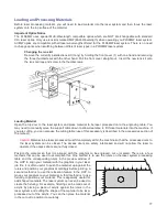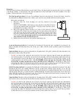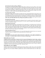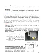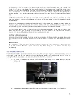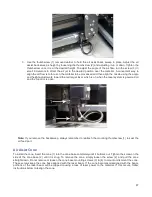
A final focusing method
is to use the auto-focus feature to focus on the material. In the Cell 2 and Cell 3
laser systems, the autofocus sensor is a light beam sensor that crosses the processing area horizontally at
about 3” inches in the Y axis. There is a notch in the Y axis ruler between the 2” and 4” marks to indicate
where the beam crosses the processing area. Make sure that a least at portion of the material to be
processed is lined up vertically with the notch blocking the light beam. If not, you may have to move the
material so it will block the light beam for auto-focus and then move it back into position for laser processing.
Then press and hold the focus button on the control panel until the autofocus process initiates. When the Z
axis stops moving the material is focused.
Important Note:
Make sure the lens specified in the system tab of the UCP matches the lens installed in the
laser system when using this feature and that the Auto-Z function is enabled.
Caution:
In order for this method to work correctly, the Z axis must be properly homed and calibrated to the
lens being used. To verify this, move the Z axis manually until the Z axis position reads zero and use the
manual focus tool as described in the manual focus section above to verify that the surface of the engraving
table is at the focus plane. If necessary, re-home the Z axis using the home Z command in the UCP viewer
tab and re-check. If you are still having trouble, recalibrate the lens using the lens calibrate function in the
system tab of the UCP.
Initiating laser processing
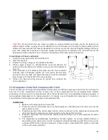
Once the material is placed and focused, you are ready to initiate laser processing of the selected laser job file. If
you need to use air assist for the material to be processed, make sure you have an air assist cone or backsweep
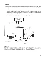
installed on the carriage and the ULS computer Controlled Compressed Air Unit is properly connected (see the
accessories section for details). Also ensure that your exhaust system is on and exhaust air is flowing through the
machine. Then start the laser job by pressing the start button on the control panel or in the UCP.
Caution:
Make sure proper exhaust flow is present in the laser system before initiating laser processing. If
proper exhaust flow is not present, damage to optics and other laser system components can occur very
quickly.
79
Summary of Contents for PLS4.75
Page 1: ...PLS User Guide PLS4 75 PLS6 75 PLS6 150D PLS6MW www ulsinc com Revision August 2012...
Page 5: ...Chapter 1 Specifications 5...
Page 8: ...Chapter 2 Safety 8...
Page 14: ...Tamper Proof Labels Safety Labels...
Page 15: ...ULS Fiber Laser Cartridge Labels 15...
Page 16: ......
Page 17: ...PLS4 Back View 17...
Page 18: ...PLS6 Front View 18...
Page 19: ......
Page 22: ...Chapter 3 Installation 22...
Page 40: ......
Page 48: ...Chapter 4 Operation 48...
Page 83: ...Chapter 5 Accessories 83...
Page 99: ...Example Connection for PNP mode Example Connection for NPN mode 99...
Page 111: ...Chapter 6 Maintenance 111...
Page 119: ...www ulsinc com...


