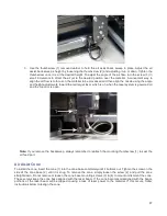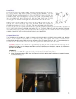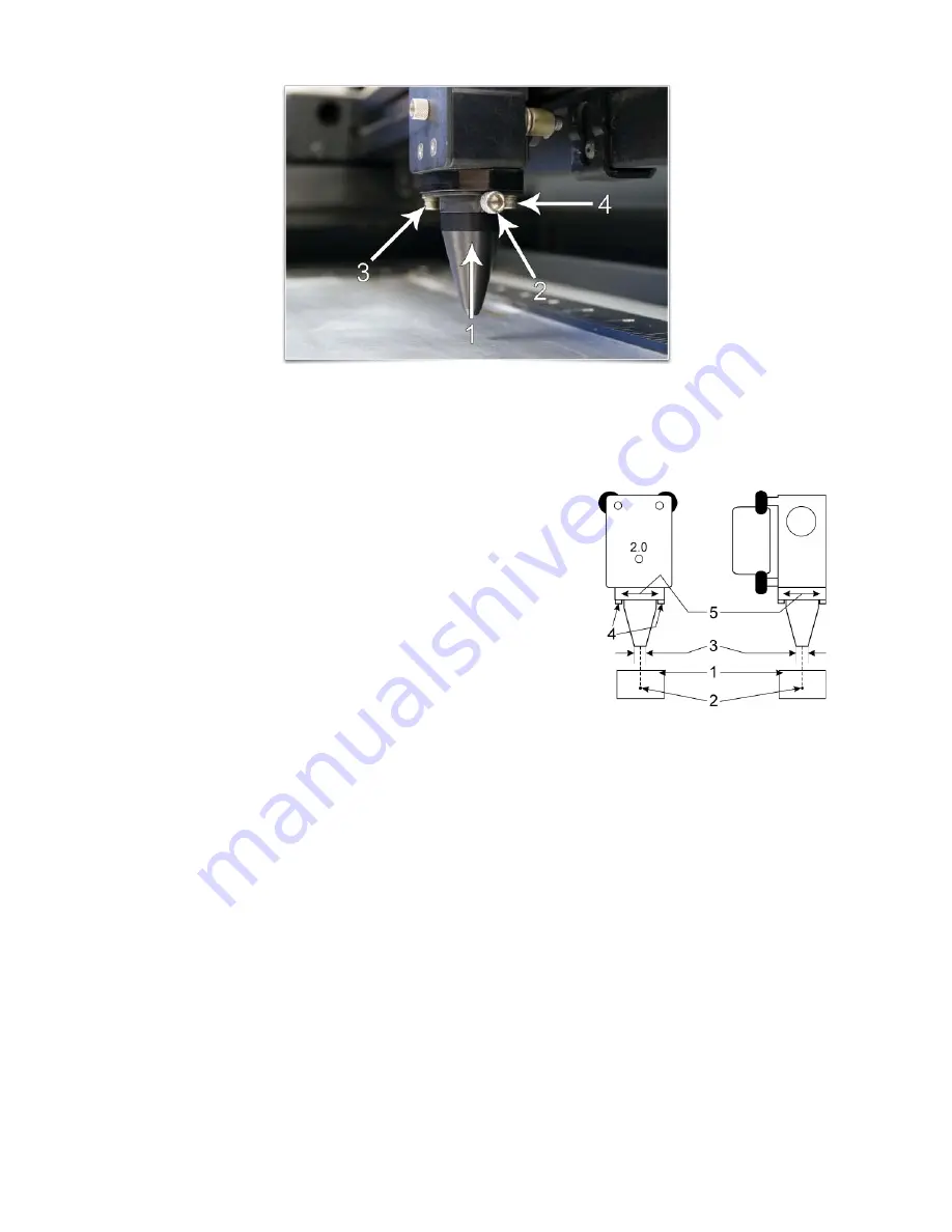
CAUTION
: Do not install the cone unless you plan on using Air Assist and never use the Air Assist Cone
without proper airflow. Leaving the cone attached to the cone base and running the laser system without
airflow will cause smoke from laser processing to be drawn up into the cone and rapidly damage the focus
lens. Also remember to make sure the back sweep mounting screw is installed in the air feed hole for the
back sweep when using the cone so air does not escape out the back sweep air feed port.
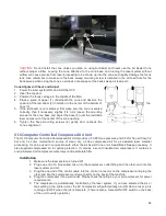
Cone Alignment Check and Adjust
1. Power the laser system ON and start the UCP.
2. Open the top door.
3. Position the focus carriage in the middle of the field.
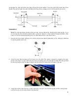
4. Place a piece of paper (1) underneath the cone and observe the
position of the red beam (2) in relation to the center of the bottom of
the
cone (3).
5. If the red beam is not centered, first make sure the cone is seated
correctly, then if necessary, slightly (1/4 turn) loosen the mounting
screws for the cone base and adjust the base (5) until the red diode
laser comes out of the center of the cone opening.
6. Tighten the base mounting screws (4) gently and re-check the
cone’s alignment.
ULS Computer Controlled Compressed Air Unit
The ULS Computer Controlled Compressed Air Unit provides a 50 PSI max pressure and 2.0 cfm free air flow (3.2
bar and 3.2 cubic meters/hour) source of clean, dry, oil free compressed air for air assisted laser material
processing. It can be used in conjunction with either the Air Assist Cone or Air Assist Back Sweep accessory. It
also supplied compressed air for optics protection. It contains a sound insulated air compressor. It contains a
sound insulated air compressor, water dryer and particulate filter.
Installation
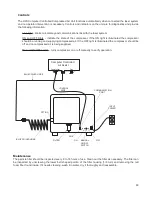
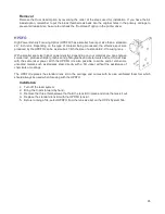
1. Make sure the laser system is turned off.
2. Plug one end of a blue coiled hose into the compressor outlet fitting and the other end into the
laser system air inlet.
3. Plug the one end of the control cable into the control connector on the compressor and plug the
other end into the compressor control connector on the back of the machine.
4. Plug the compressor into a wall outlet. Please check the rating on your air compressor for power
requirements.
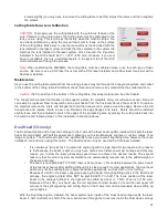
5. The compressor is automatically controlled by the laser system. If you have selected the Air or
Gas setting in the printer driver, the Air Compressor will automatically turn ON when a laser job is
running and OFF when the job is complete. (There is also a manual ON/OFF switch on the back
of the unit to verify operation).
88
Summary of Contents for PLS4.75
Page 1: ...PLS User Guide PLS4 75 PLS6 75 PLS6 150D PLS6MW www ulsinc com Revision August 2012...
Page 5: ...Chapter 1 Specifications 5...
Page 8: ...Chapter 2 Safety 8...
Page 14: ...Tamper Proof Labels Safety Labels...
Page 15: ...ULS Fiber Laser Cartridge Labels 15...
Page 16: ......
Page 17: ...PLS4 Back View 17...
Page 18: ...PLS6 Front View 18...
Page 19: ......
Page 22: ...Chapter 3 Installation 22...
Page 40: ......
Page 48: ...Chapter 4 Operation 48...
Page 83: ...Chapter 5 Accessories 83...
Page 99: ...Example Connection for PNP mode Example Connection for NPN mode 99...
Page 111: ...Chapter 6 Maintenance 111...
Page 119: ...www ulsinc com...

