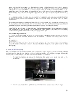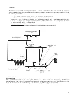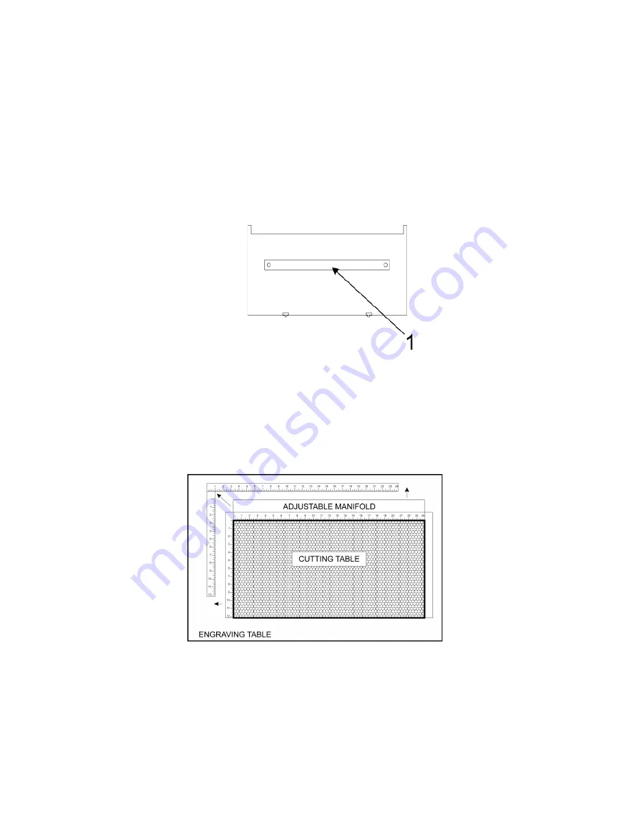
Cutting Table
The cutting table is used to support material when cutting so that exhaust flow is redirected both above and below
the material for clean cuts. Without it, smoke and debris can build up underneath the material and cause the
surface of the material to be damaged. The cutting table also helps to reduce damage to the surface of the
material from laser back reflection which can occur when the laser reflects off of the table supporting the material
if you attempt to cut without the cutting table. The cutting table is installed directly on top of the engraving table.
Installation
1. Turn on your laser system.
2. Lower the table to the bottom of its travel.
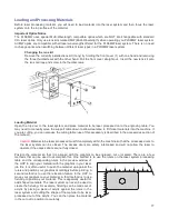
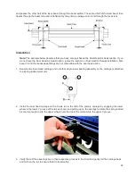
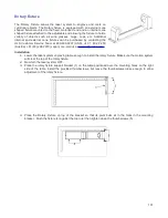
3. Remove the strip(s) from the exhaust plenum(s) (1) with a screw driver.
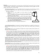
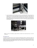
4. Before installing the cutting table in the laser system, loosen the duct adjusting thumb screws on the side
of the cutting table just enough to allow the manifold to slide in and out. Extend the adjustable manifold
out as far as it can go.
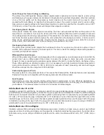
5. Open the front door of the laser system and carefully insert the cutting table into the laser system, so that
the four feet on the bottom of the cutting table are resting on the engraving table in the laser system. Then
slide the table back and to the left until the two rear feet are up against the X axis ruler and the left rear
foot is up against the Y axis ruler. The feet of the cutting table must be aligned properly with the X and Y
rulers in the laser system in order to ensure that the rulers on the cutting table line up with the processing
field.
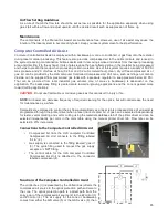
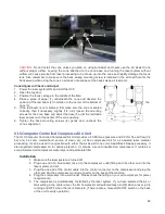
6. Make sure the adjustable manifold is squarely up against the exhaust plenum in the back of the machine
to ensure good exhaust flow below the material and tighten the four screws on the side of the cutting
table. Be careful not to move the cutting table while tightening the screws.
7. You can use the red pointer diode to ensure the cutting table is aligned to the processing field, by moving
the red pointer around the edge of the field using the manual motion keys. If the cutting table is not
aligned, check that the feet are properly pressed against the X Y rulers in the machine. If the feet are
properly positioned and the rulers are still not aligned, you can adjust them by loosening their mounting
90
Summary of Contents for PLS4.75
Page 1: ...PLS User Guide PLS4 75 PLS6 75 PLS6 150D PLS6MW www ulsinc com Revision August 2012...
Page 5: ...Chapter 1 Specifications 5...
Page 8: ...Chapter 2 Safety 8...
Page 14: ...Tamper Proof Labels Safety Labels...
Page 15: ...ULS Fiber Laser Cartridge Labels 15...
Page 16: ......
Page 17: ...PLS4 Back View 17...
Page 18: ...PLS6 Front View 18...
Page 19: ......
Page 22: ...Chapter 3 Installation 22...
Page 40: ......
Page 48: ...Chapter 4 Operation 48...
Page 83: ...Chapter 5 Accessories 83...
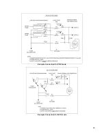
Page 99: ...Example Connection for PNP mode Example Connection for NPN mode 99...
Page 111: ...Chapter 6 Maintenance 111...
Page 119: ...www ulsinc com...

