SYSTEM OPERATION
Section 3-10
How it All Works
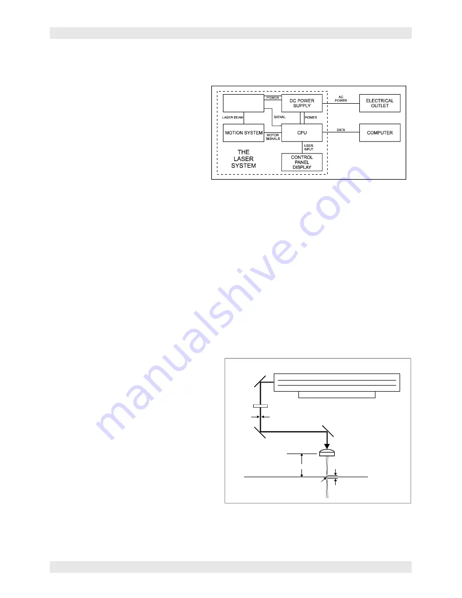
There are five (5) basic components that make up a laser system, the control panel, the CPU, the DC
power supply, the laser cartridge, and the motion system.
DC Power Supply
The DC power supply converts the incoming
AC electricity to 48 volts DC. This is used to
power both the laser cartridge and the CPU.
CPU
The CPU is the “brains” of the system and
controls everything. Located on the CPU
are standard computer memory SIMMS.
This is where incoming files, from the
computer, are stored while the power is on.
The CPU gets input from the computer and the control panel. It outputs precisely timed signals to fire the
laser beam and to move the motion system simultaneously.
LASER
CARTRIDGE
Control Panel
This is where the operator controls the laser system. It is composed of tactile feel push buttons and a
LCD display. From this panel, the operator can position the motion system, move around through the
menu system in the LCD display, and run the laser system.
NOTE: Before describing the complex functionality of the SUPERSPEED, in the following diagram,
we demonstrate how a typical single-laser system works. We will then show how the
SUPERSPEED builds upon this foundation and utilizes two laser cartridges to operate in a dual
laser single mode or dual laser dual beam mode.
Laser Cartridge
The laser cartridge is a very sophisticated device. It is composed of a plasma tube filled with a special
mixture of CO2 and other gases, and RF (radio frequency) electronics. The function of the entire
assembly is to turn electrical energy into concentrated light energy. The word LASER is an acronym for
Light Amplification by Stimulated Emission of Radiation.
The laser cartridge receives power from the
48VDC power supply and its “trigger signal” from
the CPU. When the laser system is power on
and the trigger signal comes from the CPU, the
RF electronics produce a 40 MHz signal across
the electrodes located inside the plasma tube.
This causes spontaneous photon emissions
from the gas mixture that produces an invisible,
infrared light beam at a frequency of 10.6
microns.
The laser beam exits the laser cartridge through
its output optics, reflects off the #1 mirror,
passes through the beam window, reflects off
the #2 and #3 mirrors and then finally passes
through the focus lens. The #2 and #3 mirror
and the focusing lens are all mounted to the
motion system. The width of the laser beam as
it exits the tube, called the “Beam Diameter”, is about 4 mm. The focus lens focuses the beam into a very
small spot where the spot size is dependent on the focal length of the lens. The focal length is the
distance from about the center of the lens to the point where the beam converges into the smallest spot
possible. Using a standard 2-inch focal length lens, the spot size produced is approximately .005 inches.
#2 MIRROR
#1 MIRROR
#3 MIRROR
FOCUS LENS
FOCAL RANGE
MATERIAL
FOCAL LENGTH
SPOT
BEAM WINDOW
BEAM DIAMETER
LASER CARTRIDGE
RF ELECTRONICS
GAS FILLED PLASMA TUBE
ELECTRODES
Summary of Contents for SuperSpeed-660
Page 6: ......
Page 20: ...INSTALLATION Section 2 8...
Page 34: ...SYSTEM OPERATION Section 3 14...
Page 44: ...BASIC MAINTENANCE Section 4 10...


