ACCESSORIES
Section
6-11
anifold to slide in and out. Extend the adjustable manifold
Operation
NOTE: In the following example, we will assume that your laser engraving system is a “V Platform” that
has a maximum engraving area of 24” x 18” Landscape mode.
•
Turn ON your computer (if it is not ON already). Start your graphics program, create a new graphic or
open an existing graphic.
•
Select “Print”, choose your printer (if the laser system is not set as your default), and select
“Properties” to bring up the Printer Driver settings.
•
Click on the “Engraving Field” tab and then click the “Dual Head” option box. A pop-up message will
appear asking you to verify your page size in your graphics software because the driver’s “Width” will
now be half of what it was. Make the Height less than the Width. For example, Page Orientation =
Landscape, Page Width = 12 inches, Page Height = 11 inches.
NOTE: Some graphics programs
do not allow your “Width” to be smaller than your “Height” when in the Landscape mode and
will force you page size in your graphics program to “Portrait” mode. If this is the case and
you cannot get the laser to engrave in the proper location, you might need to reduce your
“Height” to something slightly smaller than your “Width” in both the Printer Driver and the
graphics software program. In this example, we set the “Height” to 11 inches just to be safe
.
•
Adjust the page size and orientation in your graphics program to match the page size and orientation
in the driver.
•
Adjust your rulers in your graphics program so that the upper left corner of the page, on screen is the
(0,0) position.
•
Position your graphic, load your material(s) into the laser system and begin engraving.
Removal
When finished using the Dual Head, you must remove the option opposite of its installation. In the menu
system, turn the “Dual Head” option
OFF
. “If you have the Air Assist option, remember to put the black
thumbscrew back into its original hole. This will prevent the loss of air pressure in the cone of the single
head.
Honeycomb Cutting Table
The purpose of the Honeycomb Cutting Table is to support the material that you are cutting off of the
engraving table’s surface to minimize surface contact area. It also redirects exhaust airflow below and
above the material for better smoke removal. The cutting table is installed directly on top of the engraving
table. It is composed of a sheet metal box, alignment rulers, and a replaceable honeycomb style bed.
The honeycomb material is reflective only in the area that contacts your material to minimize laser beam
reflection. It can also be used as a vacuum table, providing you have a very strong exhaust blower, to
hold down slightly warped materials or materials that tend to warp during cutting or engraving.
Installation
•
Lower the table down all the way down.
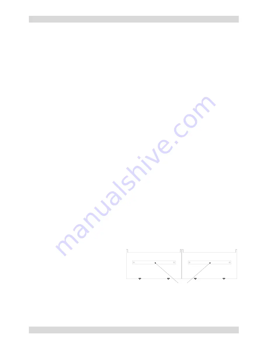
STRIPS
•
Remove the strip(s) from the exhaust
plenum(s) with an Allen wrench.
There is
one (1) exhaust plenum on the M and V
models and two (2) on the X model (as
the diagram indicates).
•
Before installing the cutting table into the
laser system, loosen the screws, without
removing them, on the side of the cutting
table, just enough to allow the adjustable m
out as far as it can go.
Summary of Contents for SuperSpeed-660
Page 6: ......
Page 20: ...INSTALLATION Section 2 8...
Page 34: ...SYSTEM OPERATION Section 3 14...
Page 44: ...BASIC MAINTENANCE Section 4 10...


