9
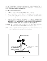
Locate laser system where a straight connection to the duct work can be achieved. A short piece
of flexible hose should be used to connect the laser system to the rigid duct work.
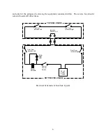
The exhaust system should be equipped with an on/off switch and wired in accordance with local
electrical codes. We recommend plugging the laser system into a 110V switched outlet,
controlled by the on/off switch for the ventilator, to ensure the laser system cannot be operated
without the ventilator. It is also advisable to power the laser system through a surge protector to
prevent damage to the electronics and laser.
Installation of the ventilation system should comply with all applicable local and government
regulations. We recommend the use of licensed contractors for installation of the exhaust
system.
2.2.2 COECTIO WITH COMPUTERS
There are two methods for establishing a connection with the computer:
•
Parallel connection (Centronics)
•
Serial connection (RS-232C)
ote:
Serial connection is not available if the High Speed Raster Engraving Option is installed.
The system is set for a parallel connection at the factory. This will work well with the majority
of computers and software packages. To change to a serial interface connection refer to the "DIP
Switch Setting Table" in Appendix A and set the DIP switch settings to match the settings
required by the software being used.
2.2.3 DIP SWITCH LOCATIO
There are two DIP switch blocks on the main control board for the laser system and the cover
must be removed to access them. Each block contains ten switches and the two blocks are
referred to as DIP Switch one and two.
1.
DIP Switch 1 - Located on the right side of the system (under top enclosure) on the printed
circuit board with the parallel and serial interface connections. DIP Switch 1, marked
"DSW1", has 10 small switches, and is located next to the parallel interface connection.
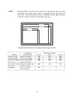
This switch is used to select the interface (parallel or serial), set field size, and character
font, etc. For details refer to "DIP Switch Setting Table" in Appendix A.
2.
DIP Switch 2 - Located on the right side of the system (under top enclosure) on the printed
circuit board with the parallel and serial interface connections. DIP Switch 2, marked
"DSW2", has 10 small switches, and is located next to DIP Switch 1.

