15
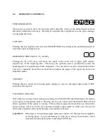
Normally this indicator is illuminated and not flashing when power to the laser system is on. If a
communication error occurs, the indicator will begin flashing. A communication error is caused
by either an improper connection to the computer or the transfer of an unknown command from
the computer. If the L.E.D. begins flashing, identify and remedy the source of the error and then
reset the system.
X-Y COORDINATE DISPLAY
Y POSITION
X POSITION
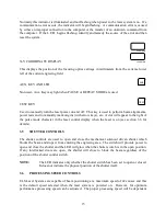
This displays the position of the focusing optics carriage in millimeters from the extreme lower
left of the current engraving field.
AUX. KEY AND LED
AUX
Not used - Aux. Key may light when PAUSE or REPEAT MODE are used.
TEST KEY
TEST
Used to manually turn the laser power on and off. This key is used to perform beam alignments,
power tests and to manually mark origins (with arrow keys), etc. A dot will appear to the right of
the pulse mode character in the laser control display when the laser is on (see section 3.6 for
details).
3.5
SHUTTER COTROLS
The shutter controls are used to open and close the mechanical solenoid driven shutter which
blocks the beam and stops it from entering the engraving area. The switch will provide power to
open and close the shutter and the LED will glow when the shutter switch is in the open position.
If any interlocked doors are open, the shutter will close to block the beam regardless of the
position of the shutter control switch.
OTE:
The LED indicates only whether the shutter switch has been set to open or closed.
It does not indicate the physical position of the shutter itself.
3.6
PROCESSIG SPEED COTROLS
ULS Laser Systems are capable of beam positioning at a maximum speed of 42 cm/sec and this
is the default speed selected when the laser system is powered on. However, for optimum
performance processing speed can be adjusted. The proper processing speed will be dependent

