22
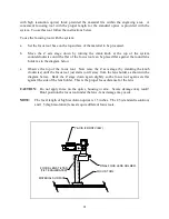
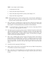
Diagram of Focus Tool Use
3.10
COMMAD SYSTEM
The ULS laser systems emulate an HP-GL plotting device and therefore are controlled by a built
in library of HP-GL Commands. The HP-GL command set used is actually RD-GL-I which is a
superset of HP-GL commands written by Roland Digital Corporation. Some of the
characteristics of this command language are listed below.
1.
There are 56 types of command.
2.
Several commands must be combined to execute one action.
3.
The commands can be used to write custom software applications.
4.
They permit high definition engraving. (Enlargement, reduction, origin movement,
window clipping and terminator definition among others.)
When using commercial software, the user does not need to understand RD-GL-I, since the
software will perform the conversions to RD-GL-I invisibly before outputting to the laser system.
However, if the user desires to write custom software applications, a reference manually detailing
the RD-GL-I command language is available from ULS.
3.11
VIEW POSITIO IDICATOR
A green dome light mounted on the top of the system just above the control panel will light up to
indicate that the motion system is in the home position. The home position in the upper right
corner of the engraving area is the position the motion system returns to when the machine is
idle. The indicator is useful for signaling that the laser system is finished with a task and ready to
begin a new task.
3.12
LASER PROCESSIG AREA
The range and maximum processing area of the ULS engraving systems will vary according to
the field size selected by the DIP switches.
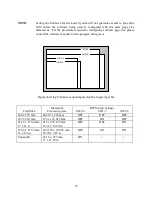
The origin of each field will lie at the bottom left corner of the field. The following table shows
the areas for each standard field size. The DIP switches are set to the expanded field size at the
factory providing the maximum processing area (17 x 11.69"). This is the most useful size for
the majority of users since it allows the full engraving area to be accessed at all times and it is
recommended that the machine be operated in this configuration. (To change the field size, refer
to Appendix A - DIP Switch Settings Table and Section 2.2.5 DIP Switch Location.)


