32
e.
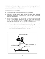
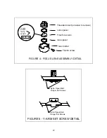
Using a small jeweler's screwdriver remove the four nylon ball tipped setscrews from
the bottom of the optics carriage (see Figure 6).
f.
While periodically looking from the front of the machine, carefully insert new nylon
ball tipped set screws into the optics carriage just far enough to start the threads but
not far enough to bring the ball tips in contact with the rail. It is helpful to place a
piece of white paper behind the Y rail to use as a background.
g.
Once all four set screws are in place, each set screw must be properly seated. This is
done by observing the gap between the ball tip of the set screw and the rail (see Figure
6) as the set screw is carefully turned forward until the ball tip just touches the rail.
Once the ball tip is just barely brought into contact with the rail turn the set screw
another 1/8 of a turn forward and no more. Repeat the procedure with each set screw.
h.
When the new set screws have been adjusted slide the optics carriage back and forth
slowly and check for smoothness. If the motion is not smooth, back each set screw
off of the rail and repeat the adjustment procedure.
2.
X Axis
a.
Move Y arm until centered in motion system.
b.
Open front door of system.
c.
Using a small jeweler's screwdriver remove the two nylon ball tipped setscrews from
the rear assembly of the Y-arm (see Figure 5).
d.
While periodically looking from the front of the machine, carefully insert new nylon
ball tipped set screws into the rear assembly of the Y-arm just far enough to start the
threads but not far enough to bring the ball tips in contact with the rail. It is helpful to
place a piece of white paper behind the Y rail to use as a background.
g.
Once both set screws are in place, each set screw must be properly seated. This is
done by observing the gap between the ball tip of the set screw and the rail (see Figure
5) as the set screw is carefully turned forward until the ball tip just touches the rail.
Once the ball tip is just barely brought into contact with the rail turn the set screw
another 3/8 of a turn forward and no more. Repeat the procedure for the other set
screw.
h.
When the new set screws have been adjusted slowly slide the Y-arm back and forth
and check for smoothness. If the motion is not smooth, back each set screw of and
repeat the adjustment procedure.

