45
3.
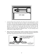
Connect the Rotary Fixture control cable to the connector on the laser engraving system. To find
the connector, follow the ribbon cable which moves with the main arm of the motion system back
to its source on the side wall up underneath the protective overhang for the main arm of the
motion system. Mounted on that side wall is the connector which the motion system ribbon cable
plugs into. The connector has two locking clasps which snap in place. Open the clasps and
disconnect the motion system cable, then plug the Rotary Fixture cable into the connector. The
connector is keyed so the cable cannot be installed incorrectly. The end of the Rotary Fixture
control cable has two plugs but only one will fit.
4.
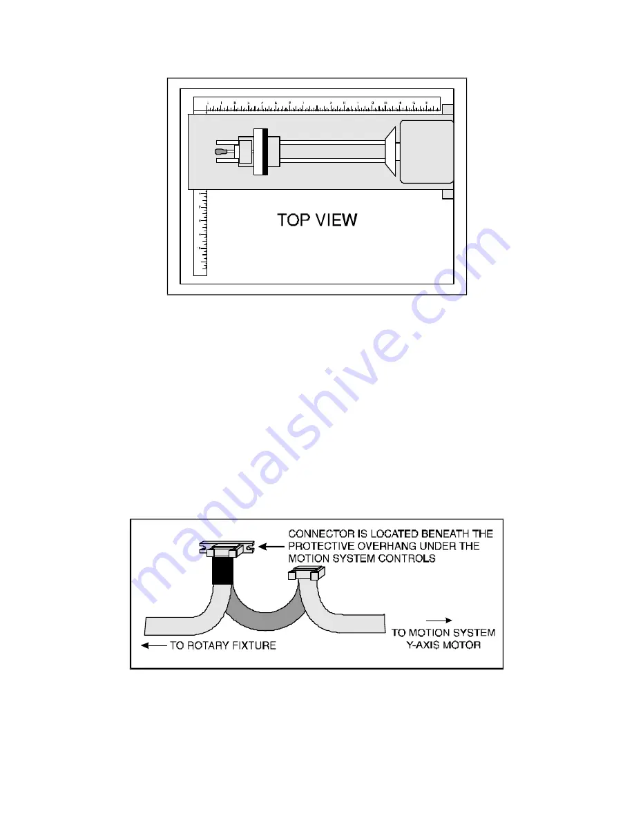
Plug the motion system cable into the free receptacle on the Rotary Fixture cable. When finished,
the Rotary Fixture cable should be plugged into the laser engraving system and the motion system
cable should be plugged into the Rotary Fixture cable. Refer to the diagram below.
Summary of Contents for ULS-25
Page 3: ...3 APPENDIX E SOFTWARE ANOMALIES E...
Page 14: ...14 Sample Exhaust System Layouts...
Page 62: ...62...
Page 82: ...A APPENDIX A WARRANTY...

