78
7.
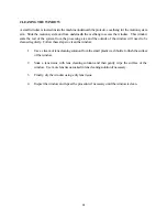
To clean the exhaust, remove the exhaust panel from the inside left wall of the system by
removing the four screws on the front of the panel. When replacing the panel, make sure to press
it tightly into place while tightening the screw so that the panel makes a good seal with the system.
8.
Check the intake air filter on the outside right wall of the system. If it is dirty, clean it by
submerging it in a mild soap solution, rinsing it clean and allowing it to air dry. If the intake filter
is allowed to become too dirty it can restrict air flow making the exhaust less effective.
9.
Clean the laser cooling fan grills and the laser fan cover.
10. Clean the top window with tissue and Windex. Do
NOT
use paper towels because they will
scratch acrylic.
5.2
HOW TO CLEAN THE OPTICS
The optical elements in the system are provided with a durable, multilayer coating that will withstand
repeated cleanings if cleaned properly. A visual inspection of the mirrors and lens should be performed
at least once a day. If a haze or debris is present on the optical surfaces, they should be cleaned. As a
general rule, if the machine itself is dirty the optical elements are probably dirty too.
Follow these instructions to clean the optics:
CLEANING THE LENS
1.
Remove the 4-40 thumb screw from the side of the lens holder located on the movable
optics carriage. Hold the lens holder while removing the screw so the holder and lens do
not drop.
2.
Inspect the lens while still in the holder. If the lens does not look too dirty or most of the
dirt seems to be on the bottom surface of the lens, leave the lens in the holder and clean
only the bottom surface using the cleaning instructions below. If the lens is extremely dirty,
it will need to be disassembled.
3.
To disassemble the lens holder assembly, (lens holder housing, threaded insert, two lens
spacers, one lens) unscrew the threaded insert while keeping the housing flat so the spacers
and lens do not fall out.
Summary of Contents for ULS-25
Page 3: ...3 APPENDIX E SOFTWARE ANOMALIES E...
Page 14: ...14 Sample Exhaust System Layouts...
Page 62: ...62...
Page 82: ...A APPENDIX A WARRANTY...

