15
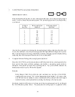
documentation included with the driver. (This driver is required if Windows is being used
and can be purchased from ULS.)
OTE:
A manually set speed will override a software speed command.
3.6
LASER COTROLS
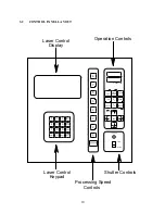
For optimum engraving performance, the ULS Laser Systems have been designed so that the
laser's power output is directed by a digital control board. This control board produces a square
wave type signal which is essentially a sequence of on and off commands which cycle the laser at
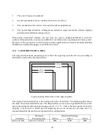
high speeds. The Laser Control keypad is used to enter the parameters for the TTL (square wave)
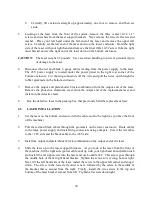
signal which drives the power output of the laser, and an LED display window is provided to
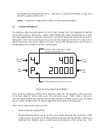
visually display the settings for the laser control signal:
This LED indicates that Laser Power is on.
This LED indicates that Power Change
option is on (see section 3.7)
Program
Number
Pulse
Mode
Pulse
Width
Pulse
Rate
Figure Showing Typical Laser Display
There are three parameters which must be entered to define the characteristics of the signal sent
to the laser, these are pulse width, pulse rate, and pulse mode. Pulse width is entered in
microseconds and defines the length of time the laser remains on during a pulse cycle. The Pulse
rate is a relative number and its meaning is dependent on the pulse mode being used.
There are two pulse modes to choose from:
•
Proportional Pulse Mode (PPM)
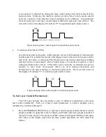
Proportional Pulse Mode will be used for most cutting and engraving operations. PPM
will provide an even exposure of laser radiation to the material and eliminate variations in
depth and line thickness due to acceleration and deceleration of the optical arm. This

