18
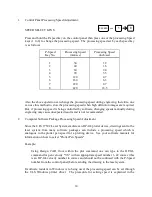
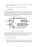
See Appendix C for suggested laser control parameters for several common materials.
CAUTIO:
The laser control parameters and speed of processing all effect the final results. It
is recommended that experimentation be done on a trial piece of material until
desirable results are obtained.
3.7
SOFTWARE COTROLLED POWER CHAGE (optional)
The ULS Laser Engraving Systems have the optional ability to accept software commands to
change power settings before and during engraving, which comes from the fact that the laser
systems emulate an HP-GL plotting device. This ability is best understood by an analogy to a
plotting device. The program numbers mentioned in section 3.6 can be thought of as pen
numbers and when a color in a software package is assigned a pen number that color will be
engraved using the Pulse settings stored in the corresponding program number. Once the power
settings have been stored in programs as described in section 3.6, accessing a power setting using
software is only a matter of assigning the appropriate color to a particular portion of a drawing.
The color/pen number combinations vary from software package to software package and it is
best to consult your software manual to find out which colors correspond to which pen numbers
in a particular piece of software. Many software packages also give the user the ability to assign
a color or several colors to a pen. If Microsoft Windows is being used, the color pen/number
combinations are found in the ULS Windows Printer Driver. Use of the driver is explained in the
documentation which accompanied it. (This driver is required if Windows is being used and can
be purchased from ULS.)
The power change option can be turned on and off by pressing a sequence of keys. If the option
is turned of the machine will operate in manual mode as described in section 3.6. To turn the
option on, press in sequence the 0 and 8 keys and to turn the option off, press in sequence the 0
and 9 keys. A dot will appear on the display to the right of the program number to indicate that
the option is turned on.
3.8
FOCUSIG PROCEDURE
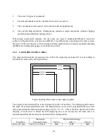
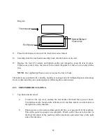
Laser Processing should be done with the laser beam focused on the top surface of the work
piece. The focal length of standard optics, provided with the system, is 2.5 inches. To find the
proper focus position for the work piece, measure the thickness of the work piece with a
micrometer and dial the Z axis crank knob to this same thickness. The numbers near the dial
indicate X axis movements in one thousandths (0.001 inch) increments.

