20
1.
There are 56 types of command.
2.
Several commands must be combined to execute one action.
3.
The commands can be used to write custom software applications.
4.
They permit high definition. (Enlargement, reduction, origin movement, window clipping
and terminator definition among others.)
When using commercial software, the user does not need to understand RD-GL-I, since the
software will perform the conversions to RD-GL-I invisibly before outputting to the laser system.
However, if the user desires to write custom software applications, a reference manually detailing
the RD-GL-I command language is available from ULS.
3.10
LASER PROCESSIG AREA
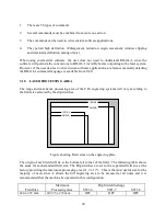
The range and maximum processing area of the ULS engraving systems will vary according to
the field size selected by the dip switches.
ANSI B
ISO A3
ISO A4
ANSI A
Figure showing Field sizes on the engraving plate
The origin of each field will lie at the bottom left corner of the field. The following table shows
the areas for each standard field size. The Dip switches are set to the expanded field size at the
factory providing the maximum processing area (11.7 x 17"). This is the most useful size for the
majority of users since it allows the full engraving area to be accessed at all times and it is
recommended that the machine be operated in this configuration.
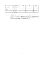
Field Size
Maximum
Processing Area
SW1-6
Dip Switch Settings
SW1-7
SW1-8
420 x 297 mm
403.95 x 276 mm
OFF
OFF
OFF

