38
2.
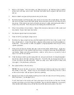
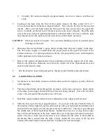
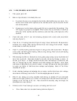
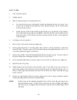
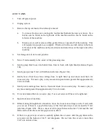
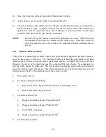
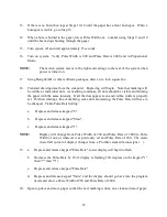
While holding Y rail (reference Figure 2) slowly rotate white nylon bearing by Y axis
motor and note friction and torque required to turn both wheels.
3.
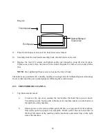
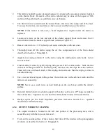
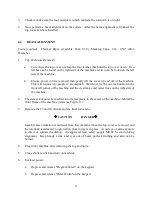
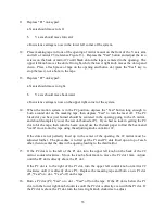
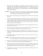
Remove the two adjusting screws under the front pulley base and remove the two belt
keepers (reference Figures 4 and 5). The two adjusting screws serve two purposes:
Attaching the belt keepers and tensioning the X axis bearings.
4.
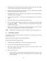
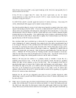
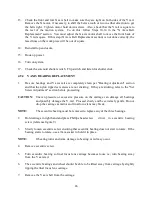
Remove the two screws from the rear support and remove the rear belt keeper (reference
Figure 6).
5.
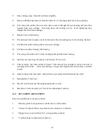
Loosen the two set screws in the shaft extension that are towards the center of the shaft
(reference Figure 7).
6.
Slide the shaft into the shaft extension until the opposite end of the shaft is approximately
half an inch out of the rear bearing.
7.
Remove belt(s).
8.
Slide new belts over shaft.
9.
Slide shaft back into bearing, put Locktite 242 on set screws, and tighten set screws in shaft
extension just so they are snug.
10. Put belt over pulley and put pulley holders back in place. Secure with two socket head cap
screws (reference Figures 2 and 3).
11. Ensure front and rear of Y arm is square with calipers (reference Figure 7). The Y arm
must be square to within 10 thousandths at this point. Replace rear support belt keeper
with two screws and Locktite 242 (reference Figure 6).
12. Replace two front belt keepers with two screws keeping Y arm square front to back.
Tighten keepers until friction of white X bearings is the same as before belt removal.
OTE:
Bearings should slip but both should have an equally stiff feel.
13. Move Y arm all the way to the left. Check front and rear gap between Y arm and left front
rail with calipers. Loosen the two center shaft extension set screws. Hold the X axis motor
pulley (front pulley) with one hand and turn the rear pulley until the Y rail, to the left frame
rail, gap is the same. Tighten the shaft extension set screws. The front and rear of the Y
arm should be the same distance from the left motion system frame rail, within +4
thousandths.
14. To check the accuracy of the Y rail squareness adjustment, first install interlock then plug
in the system. Turn on the machine and hit P1. Adjust the control panel for 150. 15000 P
mode and store it. Place a large sheet of paper on the material table. Draw a vertical line


