5.
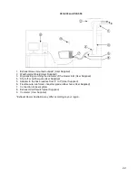
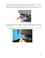
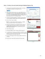
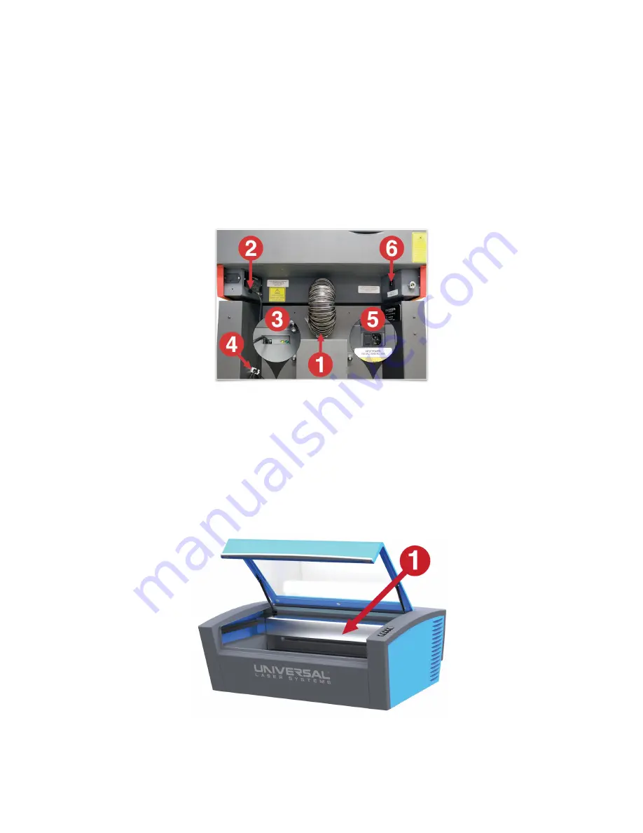
Bend and connect the short exhaust hose (1) provided with the air filtration unit to the exhaust port on the
back of the laser system and secure it with the provided hose clamps. Once the hose is attached, install
the provided sheet metal cover over the exhaust hose.
6.
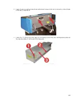
Attach a power cord to the air filtration unit’s power inlet (5), but do not plug into power outlet at this point.
7.
Connect the provided 3 ft. communications cable between one of the two Serial ports (2) of the laser
system and the Serial port connector on the air filtration unit (3). Secure the Serial cable using the
retainer clips (4).
8.
Attach a power cord to the laser system’s power inlet (6), but do not plug into power outlet at this point.
9.
Continue to next section
Laser System Assembly
1. Unpack the laser system, place it on the table or desktop where you intend to operate it (if not using the
optional exhaust air filtration unit) and open the top door and remove any packaging from inside the
machine.
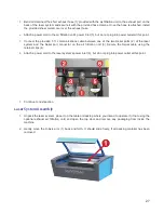
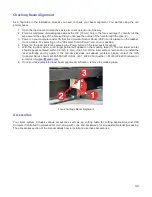
2. Gently move the X-Axis arm (1) back and forth. It should slide freely, if all packing material has been
removed.
27
1
Summary of Contents for VLS2.30
Page 1: ...VLS Desktop User Guide VLS2 30 VLS3 50 www ulsinc com Revision 2012 08...
Page 5: ...Chapter 1 Specifications 5...
Page 8: ...Chapter 2 Safety 8...
Page 9: ......
Page 15: ......
Page 16: ......
Page 19: ...Chapter 3 Installation 19...
Page 36: ...Chapter 4 Operation 36...
Page 62: ......
Page 68: ...Chapter 5 Accessories 68...
Page 80: ...Example Connection for PNP mode Example Connection for NPN mode 80...
Page 92: ...Chapter 6 Maintenance 92...
Page 99: ...www ulsinc com...

