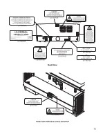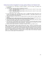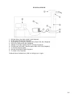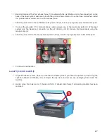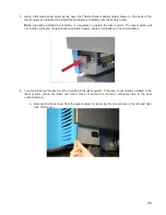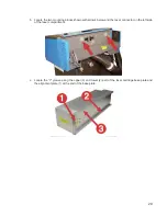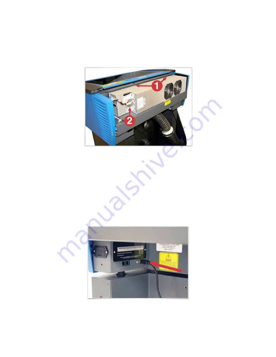
d. Pick up the laser cartridge by the ends and mount the cartridge onto the mounting blocks shown
in step b by placing the upper “V” groove on top of the mounting blocks. Slide the cartridge to the
right or left as necessary until the mounting holes in the top of the laser line up with the mounting
holes in the top of the laser mounting block.
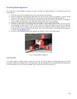
e. Attach the two supplied mounting screws marked 1 above and the laser connector marked 2.
f.
Replace the back cover.
5. Plug the laser system an optional exhaust air filtration unit, if present, into appropriate power outlets.
6. Connect the USB cable provided with the laser system between the USB port of the computer and the
USB port on the back of the laser system.
CAUTION:
The laser system is
USB 2.0 Hi-Speed (only). The laser system comes equipped with a high
quality, 6-ft (2.0 meter) USB 2.0 certified cable. We recommend you use this provided cable. Do not use
any adapters, extension cables, USB cables longer than 6 ft (2.0 meters) or other devices between the
computer’s USB port and the port on the laser system; sporadic or unpredictable behavior may result.
30
Summary of Contents for VLS2.30
Page 1: ...VLS Desktop User Guide VLS2 30 VLS3 50 www ulsinc com Revision 2012 08...
Page 5: ...Chapter 1 Specifications 5...
Page 8: ...Chapter 2 Safety 8...
Page 9: ......
Page 15: ......
Page 16: ......
Page 19: ...Chapter 3 Installation 19...
Page 36: ...Chapter 4 Operation 36...
Page 62: ......
Page 68: ...Chapter 5 Accessories 68...
Page 80: ...Example Connection for PNP mode Example Connection for NPN mode 80...
Page 92: ...Chapter 6 Maintenance 92...
Page 99: ...www ulsinc com...

