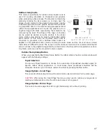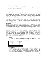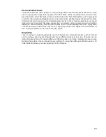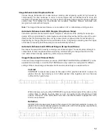
% Speed
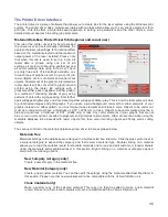
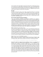
This setting allows you to select processing speed from 0 to 100%. This setting determines the maximum
rate of travel of the motion system. Actual engraving time (throughput) is not only dependent on the %
Speed setting, but is also dependent on the size, intricacy and the placement of the graphic in the
engraving field. The motion system will accelerate/decelerate at a fixed rate up to the chosen speed. If the
motion system cannot achieve the chosen speed based on the size and intricacy of the graphic or
graphical placement in the field, it will automatically adjust its speed to the maximum speed it can
achieve. This is evident when you see the motion system automatically slow down while cutting curves or
circles as opposed to straight lines. Automatic proportional pulsing (see PPI) of the laser beam will ensure
that there is no difference in the depth of cut from straight lines to curves.
% Power and % Speed work together in determining how deep the engraving or cutting will be. Higher
power and slower speeds produce deeper results. Lower power and higher speeds produce shallower
results.
Note:
100% raster speed is different than 100% vector speed. Rastering is done with the X axis focus
carriage which is light weight and has a high acceleration and top speed. Due to the inertia of the X-Axis
arm, movements in the Y-direction have a slower acceleration and top speed making vector speeds range
from one-third to one-half the maximum raster speed.
PPI
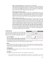
This setting allows you to select the pulsing frequency of the laser pulse stream being applied to the
material when vector cutting from 1 to 1000 pulses per inch (PPI). The PPI setting indicates how many
laser pulses, per linear inch, the laser cartridge will emit. The pulsing of the laser beam is electronically
linked to the motion. These pulses will always fire, equally spaced, from one to the next, regardless of
changes in speed. Higher PPI settings may cause more melting, burning or charring on the edges when
cutting. Lower PPI settings may reduce this effect, but may result in a serrated looking edge. Using less
than 150 PPI may result in the pulses being spread so far apart that they may or may not touch one
another creating a perforated effect. A PPI setting between 300 to 500 PPI is a good nominal value for
most applications, but some experimentation may be necessary.
Note:
In raster mode, PPI is controlled by the image density selected for rasters (image densities 5 and
below fix pulses at 500 PPI and image densities 6 and 7 fix pulses at 1000 PPI).
Mode (Drop Down Menu)
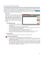
Mode allows you to force graphical elements mapped to that color to be treated in a certain way. The
choices are Rast/Vect, Rast, Vect and Skip. Rast/Vect mode is the default setting and will interpret
elements in the graphic being printed that are mapped to that color as rasters or vectors depending on
line width. Vectors must have a line width of .001” (.0254 mm) or less, everything else will be treated as
raster objects. Rast mode will force all elements of the graphic mapped to that color to be converted to
raster objects including thin line widths. Vect mode will ignore (not print) raster elements mapped to that
color and only print vector objects mapped to that color. Skip will cause all elements of the graphic
mapped to that color to be ignored (not printed).
Z-Axis
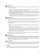
This control lets you set the Z-Axis table to a specific height. When the auto Z feature is turned on in the
UCP and a Z height is set for a color in the color table, the table moves to the height indicated before
processing the elements in the print job graphic that were mapped to that color. This feature can be used
as a method of focusing by entering the thickness of the material to be processed. This feature requires
that the Z axis be calibrated to the focus lens being used and properly homed prior to running the job.
Set Button
After adjusting all of the color based settings for the colors highlighted you must push the SET button to
register the changes to the color table. Also note that the changes will not be permanently saved until the
OK or APPLY buttons are pressed.
44
Summary of Contents for VLS2.30
Page 1: ...VLS Desktop User Guide VLS2 30 VLS3 50 www ulsinc com Revision 2012 08...
Page 5: ...Chapter 1 Specifications 5...
Page 8: ...Chapter 2 Safety 8...
Page 9: ......
Page 15: ......
Page 16: ......
Page 19: ...Chapter 3 Installation 19...
Page 36: ...Chapter 4 Operation 36...
Page 62: ......
Page 68: ...Chapter 5 Accessories 68...
Page 80: ...Example Connection for PNP mode Example Connection for NPN mode 80...
Page 92: ...Chapter 6 Maintenance 92...
Page 99: ...www ulsinc com...


