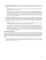
1-Touch Laser Photo Switch
This switch is automatically selected when printing photos from Universal Laser Systems 1-touch
Photo laser photo printing software. This switch also be selected when printing a photo processed by
1-Touch Photo and then imported into other software before printing. This switch optimizes settings
for best results with 1-Touch Photo images.
Image Density
The Image Density setting determines how many lines of pixels (or dots) per vertical inch are used to
render a raster image on the material being laser marked or engraved. It can also be referred to as the
vertical resolution or dpi of the image. There are seven image density choices available in most models
(two extra density levels are available in SuperSpeed models). Higher Image Density (DPI) settings
produce better quality raster images with finer detail, but reduce productivity by increasing raster
engraving time. Lower Image Density (DPI) settings produce lower quality raster images, but increase
productivity by decreasing raster engraving time.
Image Density (DPI) settings will also have an effect on vector quality and processing speeds when
vectors objects contain many curves and small segments. Higher image densities will produce finer vector
detail, but may reduce productivity and vice versa for lower image densities. By running samples on scrap
materials and tying different density settings, you can find a compromise between throughput and image
quality that is acceptable to you.
Print Direction
The default direction is Down which begins raster engraving at the top of the field and finishes at the
bottom. On some materials you may get better results by starting at the bottom and engraving towards
the top of the field (Up) due to the fact that smoke and fumes from the engraving process travel over the
surface of the material before being exhausted and can mar the previously engraved areas.
Dithering
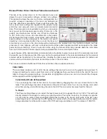
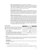
Dithering settings are used when printing graphics that contain grayscale or color bitmaps such as
photographs in all printing modes except 3D mode. A dither pattern is a special screen filter that is used to
convert a grayscale or color image to monochrome (black and white). The screen filter reduces the image
to black and white while preserving the illusion of shades of gray by varying the spacing of pixels (dots) in
the image. Darker areas have more dots spaced closer together and lighter areas have fewer dots
spaced farther apart. Since the laser system is not capable of directly reproducing color or shades of gray
this is the method used to mimic shades of gray in order to engrave or mark photographs onto material.
There are three choices for the dither pattern applied:
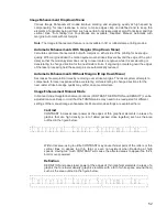
Halftone
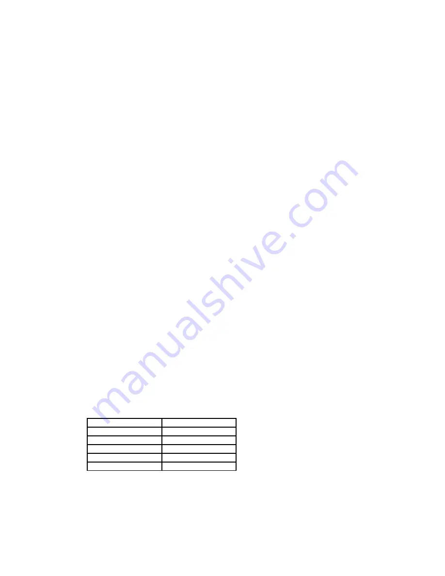
The halftone dither pattern is a line-type filter which applies a 45° line screen to a color or
grayscale image to convert it to black and white. The line spacing of the line screen varies with
the density chosen so at lower densities the line screen is more coarse.
Image Density
Lines Per Inch
6 and 7
180
5
90
4
60
3
45
2
36
Error Di
ff
usion
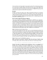
The error diffusion dither pattern uses a random scatter filter to place pixels in order to represent
shades of gray, introducing a level of noise in the process. The pattern created will vary with
density chosen. Higher density settings, such as 5, will produce a more densely packed, finer
pattern and lower resolution settings, such as 2, will produce a loosely packed, coarser pattern.
49
Summary of Contents for VLS2.30
Page 1: ...VLS Desktop User Guide VLS2 30 VLS3 50 www ulsinc com Revision 2012 08...
Page 5: ...Chapter 1 Specifications 5...
Page 8: ...Chapter 2 Safety 8...
Page 9: ......
Page 15: ......
Page 16: ......
Page 19: ...Chapter 3 Installation 19...
Page 36: ...Chapter 4 Operation 36...
Page 62: ......
Page 68: ...Chapter 5 Accessories 68...
Page 80: ...Example Connection for PNP mode Example Connection for NPN mode 80...
Page 92: ...Chapter 6 Maintenance 92...
Page 99: ...www ulsinc com...

