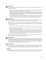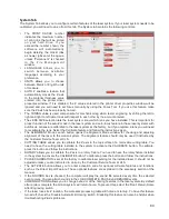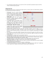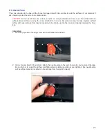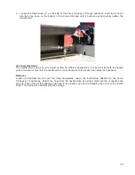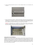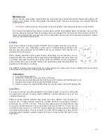
A second focusing method
is to measure the thickness of the material (use a calipers for accuracy) to be
laser processed and manually move the Z axis up or down until the Z axis position equals the measured
thickness.
Important Note:
Make sure the lens specified in the system tab of the UCP matches the lens installed in
the laser system when using this method.
CAUTION:
In order for this method to work correctly, the Z axis must be properly homed and calibrated to
the lens being used. To verify this, move the Z axis manually until the Z axis position reads zero and use
the manual focus tool as described in the manual focus section above to verify that the surface of the
engraving table is at the focus plane. If necessary, re-home the Z axis using the home Z command in the
UCP viewer tab and re-check. If you are still having trouble, recalibrate the lens using the lens calibrate
function in the system tab of the UCP.
A third focusing method
is to measure the thickness of the material (use a calipers for accuracy) to be laser
processed and enter the material thickness into the printer driver settings when printing. In materials database
printer driver, you will enter the thickness in the material thickness field. With this method, the Z axis will move
up or down to the appropriate height when you press the start button to initiate laser processing of the
selected job.
Important Note:
Make sure the lens specified in the system tab of the UCP matches the lens installed in
the laser system when using this feature and that the Auto-Z function is enabled.
CAUTION:
In order for this method to work correctly, the Z axis must be properly homed and calibrated to
the lens being used. To verify this, move the Z axis manually until the Z axis position reads zero and use
the manual focus tool as described in the manual focus section above to verify that the surface of the
engraving table is at the focus plane. If necessary, re-home the Z axis using the home Z command in the
UCP viewer tab and re-check. If you are still having trouble, recalibrate the lens using the lens calibrate
function in the system tab of the UCP.
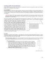
Initiating laser processing
Once the material is placed and focused, you are ready to initiate laser processing of the selected laser job file. If
you need to use air assist for the material to be processed, make sure you have an air assist cone or backsweep
installed on the carriage and the ULS Computer Controlled Compressed Air Unit is properly connected (see the
accessories section for details). Also ensure that your air filtration unit is plugged in to a power outlet and properly
connected to the laser system. Then start the laser job by pressing the start button on the control panel or in the
UCP.
CAUTION:
Make sure the air filtration unit activates and proper exhaust flow is present in the laser system
during laser processing. If proper exhaust flow is not present, damage to optics and other laser system
components can occur very quickly.
64
Summary of Contents for VLS2.30
Page 1: ...VLS Desktop User Guide VLS2 30 VLS3 50 www ulsinc com Revision 2012 08...
Page 5: ...Chapter 1 Specifications 5...
Page 8: ...Chapter 2 Safety 8...
Page 9: ......
Page 15: ......
Page 16: ......
Page 19: ...Chapter 3 Installation 19...
Page 36: ...Chapter 4 Operation 36...
Page 62: ......
Page 68: ...Chapter 5 Accessories 68...
Page 80: ...Example Connection for PNP mode Example Connection for NPN mode 80...
Page 92: ...Chapter 6 Maintenance 92...
Page 99: ...www ulsinc com...

