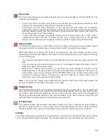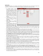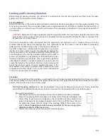
Vector Output for Vector Cutting and Marking
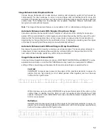
The printer driver distinguishes between raster objects (raster engraving) and vector objects (vector cutting
and marking) by the types of elements contained in the graphic being printed. All graphics, other than outlines
of very thin line widths will be interpreted as raster objects and the raster mode will be used for laser
processing. Not all software is capable of printing vector output. If you want to create jobs for vector cutting,
make sure your graphic software of choice allows creation of vector lines and that the line width can be 0.001”
(0.0254 mm) or less. The printer driver will interpret these objects as vectors.
Overlapping Raster Objects
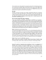
If the artwork created has raster objects that overlap, the driver will automatically filter out the portion of the
object that is not visible so that only the visible part of the underlying filled area will be engraved to prevent
the overlapped area from being engraved twice. This allows the color white to be used as an effective drawing
tool. Since the laser system will not engrave the color white (this is the background color), it can be used to
block out the undesired engraving areas of raster objects. However, you cannot use a white fill to cover a
vector outline, the outline will vector cut even though you cannot see it on screen.
Overlapping Vector Objects
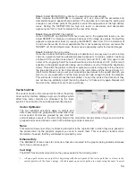
The driver does not filter vector objects that overlap each other. If you place one thin vector outline on top of
another, both outlines will be cut by the laser system. This can be useful for making multiple cutting passes in
one laser job for thicker materials.
Bitmapped Scanned Images
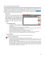
When printing raster objects such as photographs which are grayscale or color bitmaps, keep in mind that the
printer driver uses a dither pattern filter screen to reduce the images to black and white (monochrome
images) for laser processing using variable spacing between the dots to create the illusion of shades of gray.
These dither patterns are relatively coarse so it is not necessary to use high resolution bitmaps. Grayscale or
color photos should be reduced to 300 to 600 dpi for purposes of laser processing and scanned images
should be scanned into the computer at 300 to 600 dpi.
Postscript Images and Fonts
The laser system is not a postscript device. This means that Postscript fills, Postscript textures and especially
Postscript fonts are not compatible with the laser system and should be avoided.
Font Troubles
Occasionally you may have trouble printing certain fonts at certain sizes in some Windows applications. In
these cases it is helpful to export the graphic to a bitmap format, such as jpeg, and re-import it into your
software. This process forces the fonts to be converted to bitmap images.
Adobe Illustrator CS or CS2
Illustrator versions CS and CS2 do not properly support non square landscape pages. For this reason, in order to
print effectively from these programs you must set up your page size as landscape and make the width and height
both equal to the largest dimension of your laser system’s processing field. For example, if your processing field is
24” wide x 12” tall, make the page in Illustrator 24” x 24” landscape. You can then treat the upper left corner of the
illustrator page as the zero-zero point in the laser system processing field and only use the upper half of the page
in illustrator. Anything in the lower half of the page will not be printed. Also make sure you are using an RGB color
palette and the vector line stroke width is set to .001” (.0254 mm) or less.
Adobe Illustrator CS3 and higher
Illustrator versions CS3 and higher treat landscape page sizes correctly, but make sure you select user defined
page size at time of printing and make sure the page size in Illustrator matches the page size in the printer driver.
Also make sure you are using an RGB color palette and the vector line stroke width is set to .001” (.0254 mm) or
less.
66
Summary of Contents for VLS2.30
Page 1: ...VLS Desktop User Guide VLS2 30 VLS3 50 www ulsinc com Revision 2012 08...
Page 5: ...Chapter 1 Specifications 5...
Page 8: ...Chapter 2 Safety 8...
Page 9: ......
Page 15: ......
Page 16: ......
Page 19: ...Chapter 3 Installation 19...
Page 36: ...Chapter 4 Operation 36...
Page 62: ......
Page 68: ...Chapter 5 Accessories 68...
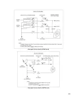
Page 80: ...Example Connection for PNP mode Example Connection for NPN mode 80...
Page 92: ...Chapter 6 Maintenance 92...
Page 99: ...www ulsinc com...

