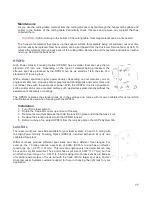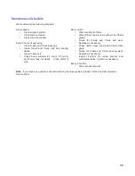
Rotary Position Calibration
a
.
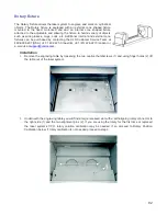
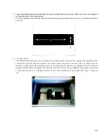
Raise the Z-Axis platform to the top of its travel (engraving table should be removed first).
b
.
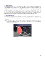
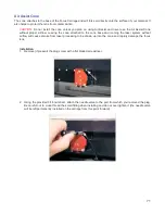
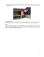
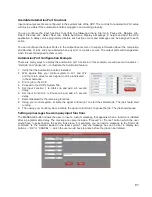
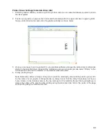
In the UCP Viewer Tab, select the Focus Feature on the Viewer Tab. Using the mouse pointer
and the manual motion keys in the UCP move the carriage manually and center red alignment
pointer on the right alignment pin.
c
.
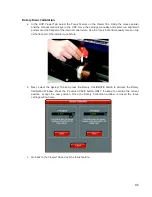
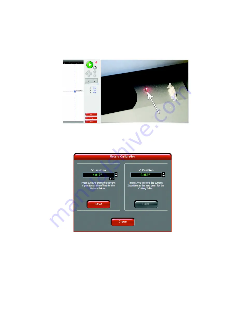
Next, select the System Tab and press the Rotary CALIBRATE button to activate the Rotary
Calibration Window. Press the Y position SAVE button while the red alignment laser is still located
on the right alignment pin. If asked to override the current position, accept the new position. Once
the Rotary Calibration window is closed the focus carriage will re-home.
d
.
Go back to the Viewer Tab and exit the focus feature.
83
Summary of Contents for VLS2.30
Page 1: ...VLS Desktop User Guide VLS2 30 VLS3 50 www ulsinc com Revision 2012 08...
Page 5: ...Chapter 1 Specifications 5...
Page 8: ...Chapter 2 Safety 8...
Page 9: ......
Page 15: ......
Page 16: ......
Page 19: ...Chapter 3 Installation 19...
Page 36: ...Chapter 4 Operation 36...
Page 62: ......
Page 68: ...Chapter 5 Accessories 68...
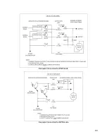
Page 80: ...Example Connection for PNP mode Example Connection for NPN mode 80...
Page 92: ...Chapter 6 Maintenance 92...
Page 99: ...www ulsinc com...

