7.
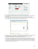
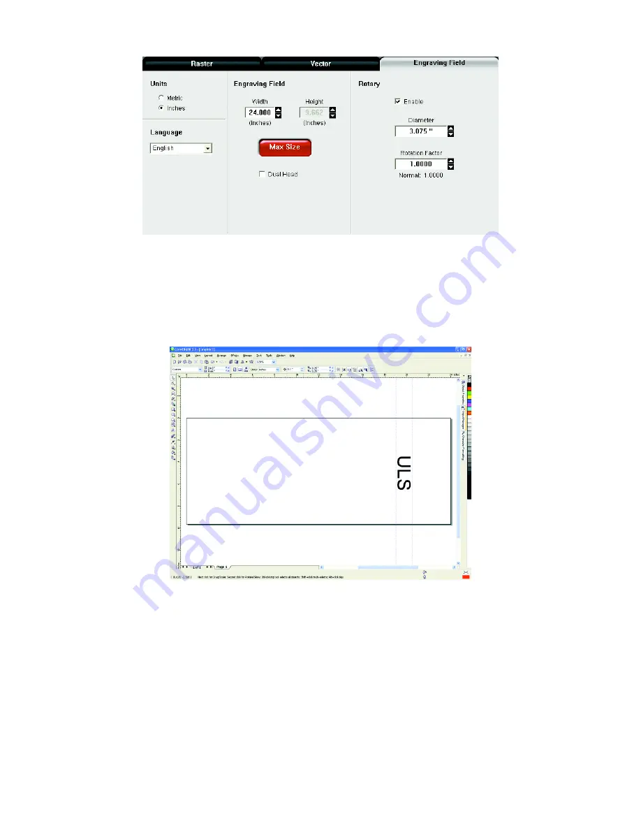
Once you have the new engraving field size, exit the printer driver properties dialog.
8.
In your graphics software change the page size to equal the new engraving field size from the printer
driver dialog.
9.
This new vertical dimension of the page is now the circumference of the material to be engraved.
10.
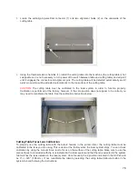
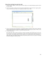
Position your graphic on page so that it is located horizontally within the upper and lower engraving limits
that you determined earlier and center the graphic vertically as shown below.
11.
Once you are ready to print, select print in your graphics software and check to make sure rotary mode is
still enabled and the correct diameter for your material is still entered in the printer driver dialog.
12.
Then set the appropriate power and speed settings before printing the job.
Note: Remember, before running a rotary job, to rotate the material by hand until the position you want to
be the center of your graphic is facing directly up. Keep in mind that the rotary fixture does not have a
home location in the rotational axis so the top most part of the material (the part facing straight up) is
always the center of the graphic when printing using the materials driver tab or the center of the page
when printing using the manual driver tab.
88
Summary of Contents for VLS2.30
Page 1: ...VLS Desktop User Guide VLS2 30 VLS3 50 www ulsinc com Revision 2012 08...
Page 5: ...Chapter 1 Specifications 5...
Page 8: ...Chapter 2 Safety 8...
Page 9: ......
Page 15: ......
Page 16: ......
Page 19: ...Chapter 3 Installation 19...
Page 36: ...Chapter 4 Operation 36...
Page 62: ......
Page 68: ...Chapter 5 Accessories 68...
Page 80: ...Example Connection for PNP mode Example Connection for NPN mode 80...
Page 92: ...Chapter 6 Maintenance 92...
Page 99: ...www ulsinc com...


