VLS Service Manual
Table of Contents
X-Axis
Page | 54
X-Axis
X-Axis Rail
NOTE: Place any hardware removed from the laser system and X-axis arm in a safe place.
1. Power OFF and unplug the VLS.
2. Remove
the
X-Axis Arm
and set it on a safe working surface.
3. Remove
the
X-Axis Motor
.
4. Remove the X-axis Focus Carriage as shown in the
X-Axis Bearings
section.
5. Completely remove the X-axis Belt by removing the two screws holding the belt clamp and pulling the
belt out of the rail. Please note the path the belt follows through the rail.
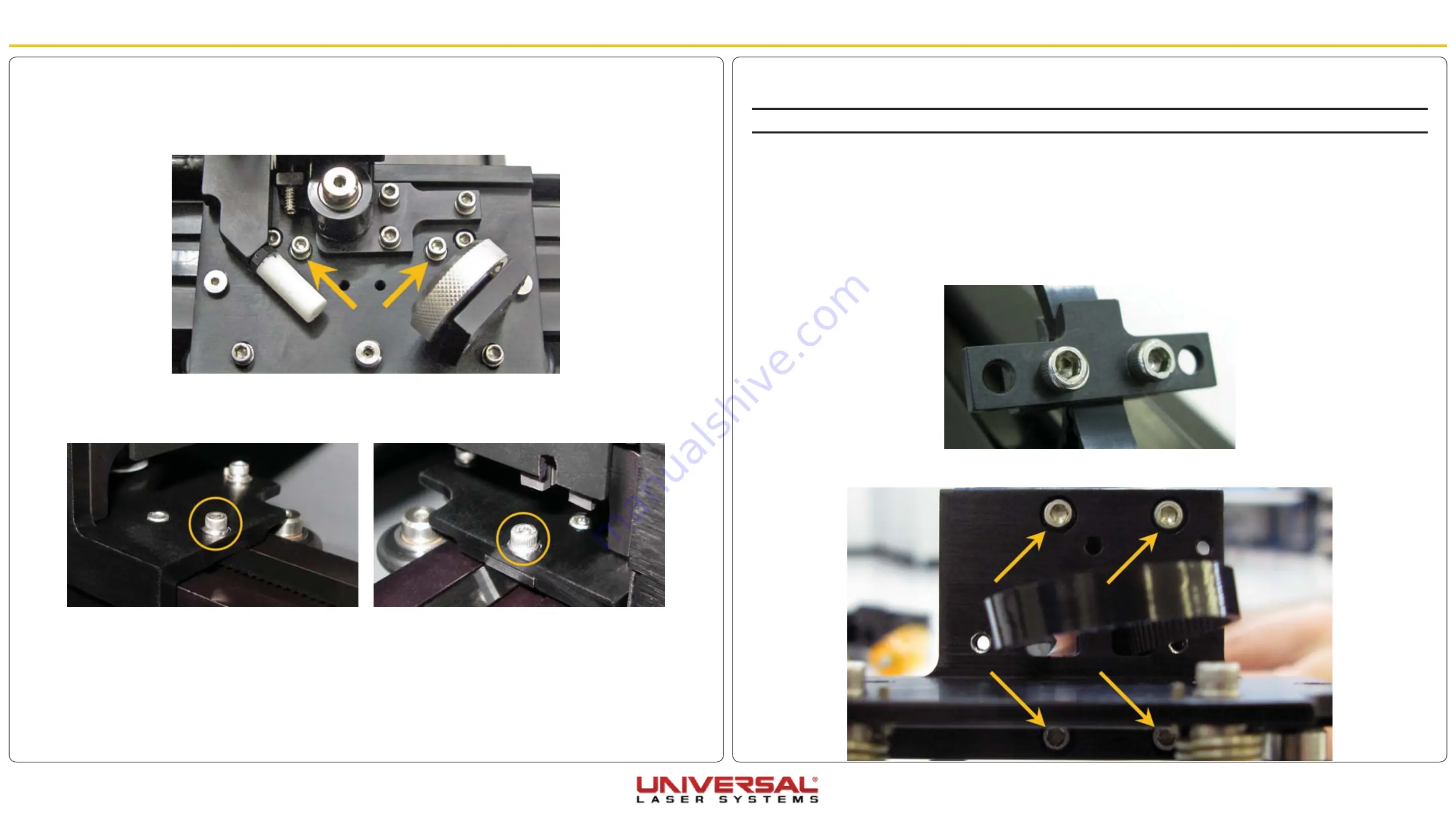
6. Remove the right end support by removing the four screws located on the top (2) and bottom (2) of the
support.
5. Remove the #2 mirror cover (1) by removing the thumbscrew (2), sliding the cover to the right and then
off the rail.
6. Unscrew the two protruding screws on the left side of the X-axis Arm near the tensioning bracket. Each
screw that is removed has 2 washers. Set those aside in a safe place.
7. Unscrew the two protruding screws on the right side of the X-axis Arm. One screw is located in front of
the X-axis motor assembly and the other is located behind the X-axis motor assembly near the Y
Sensor. Each screw that is removed has 2 washers. Set those aside in a safe place.
8. Once all four screws are removed grab hold of the right support bracket, not the X-axis motor assembly,
and push the X-axis Arm to the left then tilt it toward you.
9. Installation is opposite of removal.


