Goodrive10 inverters Installation guidelines
16
3.2 Standard wiring
3.2.1 Connection diagram of main circuit
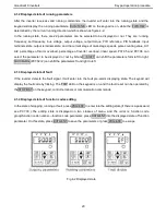
Diagram 3-3 Connection diagram of main circuit
Note:
The fuse, DC reactor, braking resistor, input reactor, input filter, output reactor, output filter are
optional parts. Please refer to
Peripheral Optional Parts
for detailed information.
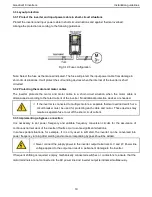
Before connecting the braking resistor cable, remove the yello w labels of
PB, (+),
and
(-)
from the
terminal blocks. Otherwise, poor connection may occur.
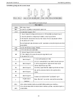
3.2.2 Terminals figure of main circuit
R/L
S/N
T/
(+)
PB
U
V
W
Fig 3-4 Terminals of main circuit
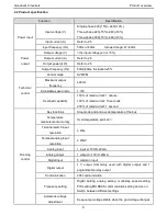
Terminal
sign
Terminal name
Function
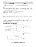
R/L
Power input of the main circuit
3-phase/single-phase AC input terminals which are generally
connected with the grid.
S/N
T
U
The inverter output
3-phase AC output terminals which are generally connected
with the motor.
V
W
PB
Braking resistor terminal
PB and (+) are connected to the external resistor.
(+)


