4
IR Series
Installation, Operation, Maintenance and Parts Manual
Detroit Radiant Products Company
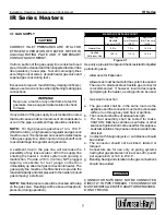
1.1 DESIGN
When positioning heater, keep in mind the clearance
to combustible materials, lights, sprinkler heads,
overhead doors, storage areas with stacked
materials, gas and electrical lines, parked vehicles,
cranes, etc. Refer to Figure 1.1 on page 3 for
minimum clearance to verify that a safe installation
condition exists.
In locations used for the storage of combustible
materials, signs shall be posted to specify the
maximum permissible stacking height to maintain
required clearances from the heater to the
combustibles.
1.2 LAYOUT
Perimeter mounting of these infrared heaters
provides for the most efficient installation. In Figure
1.5, the heaters are mounted around the perimeter
of the space to be heated. Refer to the Installation
Chart for the recommended distances on the models
being installed.
Buildings that require the rows of heaters to be farther
apart than the recommended distance in the
Installation Chart may need additional heaters placed
in the center of the space as in Figure 1-5.
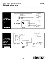
Typical exhauster, air intake louver and thermostat
location is also shown on the sample buildings in
Figure 1.5.
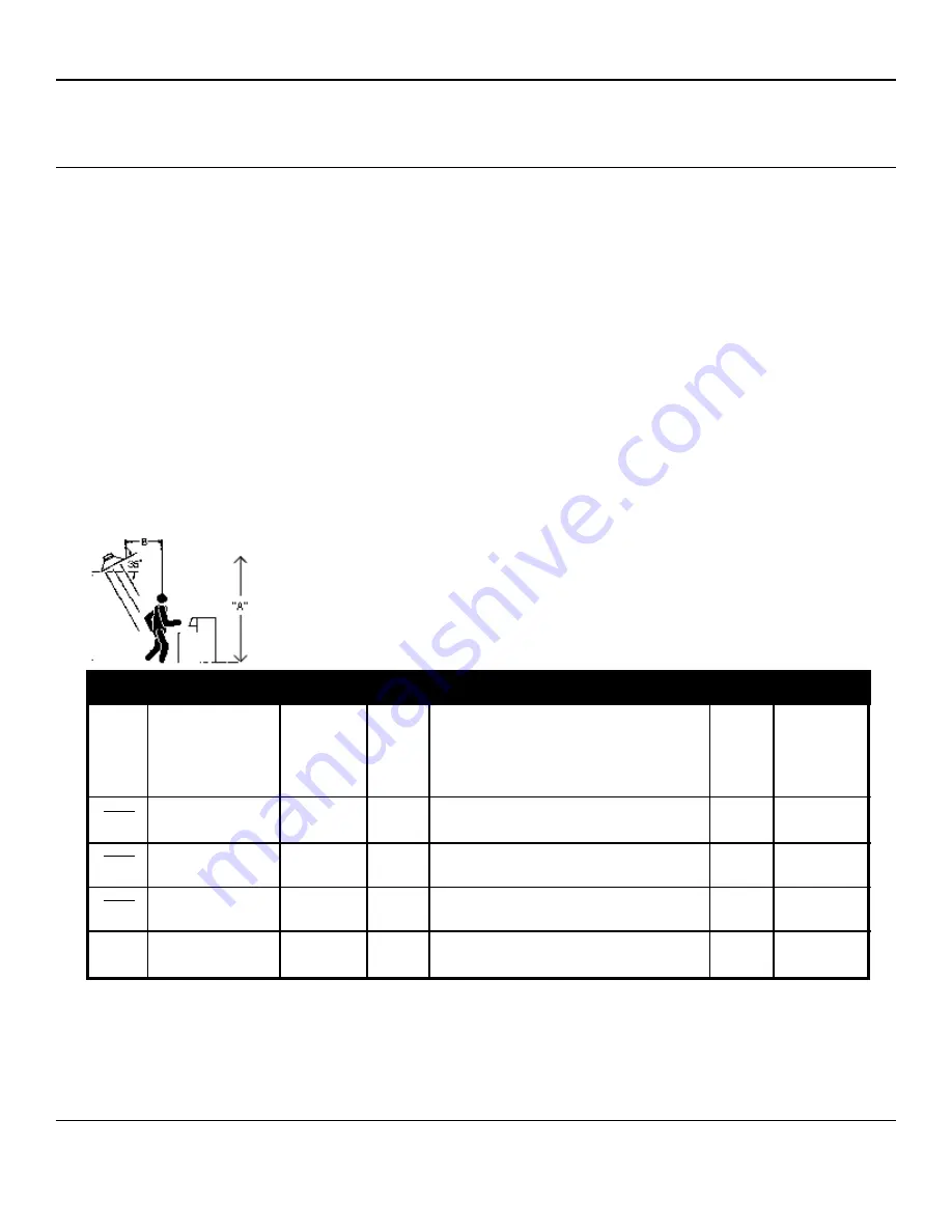
Figure 1.3
IR SERIES SPOT HEATER LOCATION CHART
MODEL
&
INPUT
IR-30
30,000
BTU/H
IR-60
60,000
BTU/H
IR-90
90,000
BTU/H
TYPE AREA
(SURROUNDINGS)
COLD/DRAFTY
AVERAGE
PROTECTED/INSUL.
COLD/DRAFTY
AVERAGE
PROTECTED/INSUL.
COLD/DRAFTY
AVERAGE
PROTECTED/INSUL.
APPROX.
DIMENSIONS
OF AREA
COVERED
10’ X 10’
12’ X 12’
14’ X 14’
16’ X 16’
18’ X 18’
20’ X 20’
20’ X 20’
24’ X 24’
28’ X 28’
APPROX.
SQ. FT.
COVERED
1 00
1 44
1 96
2 56
3 24
4 00
4 00
5 76
7 84
APPROX.
CENTERS FOR
FULL
COVERAGE
(SPOT & AREA)
HTG. ONLY
10’
12’
14’
16’
18’
20’
20’
24’
26’
’
32’
35’
“B” DIM.
DISTANCE
BEHIND
MAN OR
WORK
STATION
4 ’
5 ’
6 ’
6 ’
7 ’
8 ’
RECOMMENDED MOUNTING HEIGHT
(“A” DIM.)
10’ 12’ 14’ 16’ 18’ 20’ 22’ 24’ 26’ 28’ 30’
9 ’
10’ 12’
12’ 14’
12 14’
14’ 16’
16’ 18’
16’ 18’
18’ 20’
20’


