background image

6

IR Series

Installation, Operation, Maintenance and Parts Manual

Detroit Radiant Products Company

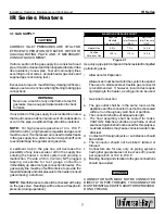
Figures 2.1 and 2.2 illustrate the more commonly
used methods for heater mounting.  Figure 2.1
shows the fastest and most economical method.
Some local codes or application conditions, such
as drafts that could cause units to swing,
stipulate that if flexible gas connectors are
used then the heaters must be rigidly mounted
(Figure 2.2)

Heater must be level from side to side (see Figure
1.2 on pg. 3).  The units must be mounted at a
20° to 35° angle from horizontal
, so the controls
(or manifold end) are located at the lower end
(Figure 2.3-2.5). Gas and electrical lines must not
be located above the path of exhaust.

2.1  HEATER MOUNTING

Figure 2.1 TYPICAL HEATER MOUNTING

Figure 2.2 RIGID HEATER MOUNTING

Figure 2.3 BURNER ASSEMBLY RELATION

TO GROUND LEVEL

Figure 2.4 BURNER ASSEMBLY RELATION

TO GROUND LEVEL

Figure 2.5 BURNER ASSEMBLY RELATION

TO GROUND LEVEL

Proper

Incorrect

Optional 325-3 regulator required

where gas supply pressure

exceeds 14” W.C.P

Do not install gas piping
or electrical wiring above
flue discharge area.

Summary of Contents for IR 30 (S)

Page 1: ...w the gas supplier s instructions If you cannot reach your gas supplier call the fire department Form LIOIR 1M 11 03 HH DETROITRADIANTPRODUCTSCOMPANY Detroit Radiant Products Company IR Series ENGLISH WARNING Improper installation alteration service or maintenance can cause property damage injury or death Read the installation operating and maintenance manual thoroughly before installing or servic...

Page 2: ...st 8 ft above the floor The heaters must be located in areas where they will not be subject to contact by aircraft cranes moveable scaffolding or other objects CAUTION The following information should be reviewed before installing this heater If an external electrical source is utilized the heater must be electrically grounded in accordance with the National Electrical Code ANSI NFPA70 current edi...

Page 3: ...sure that these clearances will be maintained from the highest raised vehicle NOTE If the heater is mounted beneath a non combustible surface a 24 in minimum clearance must be maintained from the top of the heater to prevent overheating the controls Figure 1 2 CLEARANCE TO COMBUSTIBLES DIAGRAM Figure 1 1 CLEARANCE TO COMBUSTIBLES CHART IR Series This clearance is 80 in when the heater is fitted wi...

Page 4: ... for the recommended distances on the models being installed Buildings that require the rows of heaters to be farther apart than the recommended distance in the Installation Chart may need additional heaters placed in the center of the space as in Figure 1 5 Typical exhauster air intake louver and thermostat location is also shown on the sample buildings in Figure 1 5 Figure 1 3 IR SERIES SPOT HEA...

Page 5: ...E Dimensions A B and C refer to figure 1 4 Mounting Heights Dimension A Distance Distance Distance 30 Angle 30 Angle Between Between Between Standard Parabolic Heaters Heater Rows Heater Reflector Reflector Dimension B Dimension C and Wall ft ft ft ft ft IR 30 S 12 14 12 15 8 30 10 70 6 IR 130 12 14 12 15 8 30 10 70 6 IR 60 14 16 18 21 15 43 15 90 12 IR 90 16 18 21 25 20 55 20 110 12 HEATER INSTAL...

Page 6: ...side to side see Figure 1 2 on pg 3 The units must be mounted at a 20 to 35 angle from horizontal so the controls or manifold end are located at the lower end Figure 2 3 2 5 Gas and electrical lines must not be located above the path of exhaust 2 1 HEATER MOUNTING Figure 2 1 TYPICAL HEATER MOUNTING Figure 2 2 RIGID HEATER MOUNTING Figure 2 3 BURNER ASSEMBLY RELATION TO GROUND LEVEL Figure 2 4 BURN...

Page 7: ...ply line must be of sufficient size to provide the requiredcapacityandinletpressuretotheheater consult gas company as follows NOTE Manifold pressure should be checked at the tap on the gas valve Readings will be above atmospheric pressure during operation Useonlyapipejointcompoundthatisresistanttoliquified petroleum gases Allowance for Expansion Allowances must be made for the system to expand The...

Page 8: ...on controls If the system is not grounded to a positive source it cannot determine the presence of a flame and will lockout and shut off For wiring of controls on the unit see the wiring diagram included on the provided insert It is recommended that the thermostat be installed on the hot side of a fused supply line and have a sufficient ampere capacity rating for the heater s it will control The v...

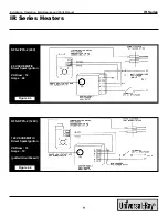
Page 9: ...ce and Parts Manual IR Series Heaters NFS 2 PFS 2 24V 24 V SCHEMATIC Direct Spark Ignition VA Draw 12 Amps 48 Figure 4 3 NFS 2 PFS 2 120V 120 V SCHEMATIC Direct Spark Ignition VA Draw 12 Amps 10 potted circuit board Figure 4 4 IR Series ...

Page 10: ...use excessive infiltration and unfavorable drafts thereby affecting efficient combustion of infrared heaters Mechanical exhausters are preferred and typically mounted at high points of the building on areas of the roof where stagnant air can accumulate under the deck For a flat roof considerations of prevailing winds high and low pressure areas and distribution of air movement must be taken into c...

Page 11: ...istance of 2 4 from the unit is recommended 3 Place the air hose outlet into each venturi tube and allow the air to flow for approximately one minute 4 See troubleshooting chart pg 12 if there are any signs of burner malfunction Replace if necessary Pilot Burner 1 Remove pilot access door 2 Use an air hose and blow the pilot burner free of dust 3 Remove pilot orifice and clean with a wire of less ...

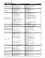
Page 12: ...d in drafty area 1 Relocate or shield from draft 2 Low gas pressure 2 See Section 3 1 Gas Supply for propane 3 Thermostat located in drafty area 3 Relocate thermostat 4 Defective flame detector 4 Replace 1 Lack of 120V or 24V incoming 1 Clean or adjust pilot voltage 2 Open high voltage wire 2 Isolate and ohm for resistance replace if 0 3 Improper electrode gap 3 See Ignition System insert 4 Loose ...

Reviews: