


14
RHT
Series
4.0
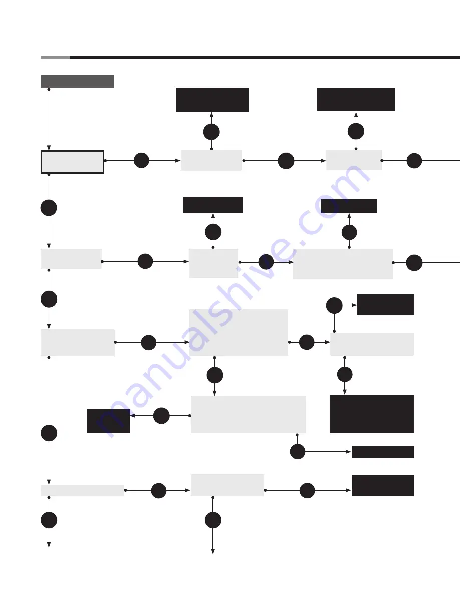
Troubleshooting Guide
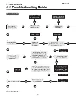
4.0
Troubleshooting Guide
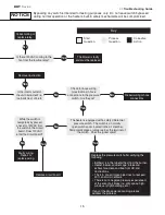
Is the valve switch in
the ON position?
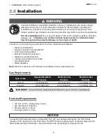
Check that gas pressure is within
minumum and maximum inputs
as indicated on the heater’s rating
plate. Is gas pressure ok?
Does the fan
blower turn on?
Is the blower
obstructed?
Turn up thermostat.
Is the power at the
heater 120VAC?
No
Remove obstruction
and lubricate blower.
Does the igniter
spark?
Is the igniter
physically
damaged?
No
Yes
Replace igniter.
Yes
No
Find the source of the
electrical problem.
Check the gap on the
igniter. Is the gap between
3/16 in. and 1/4 in.?
No
Adjust gap.
Yes
No
Yes
No
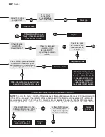
During the ignition
trial, does the gas
valve open?
Yes
Test for 24VAC at the gas
valve during valve opening
(typically 10 seconds after
power to the heater). Is
there 24VAC to the valve?
No
Yes
Is 120VAC being sent
to the transformer?
No
Does the burner light?
Yes
Correct problem.
Replace
gas valve.
Yes
No
Yes
Continued on page 16.
Yes
No
Switch to the ON
position.
Yes
The circuit board and/
or wiring harness
could be faulty. These
should be replaced.
No
No
Yes
Replace 24VAC
transformer.


