18
RHT
Series
5.0
Parts • Heater
Components and Parts List
5.0
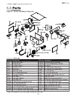
Parts
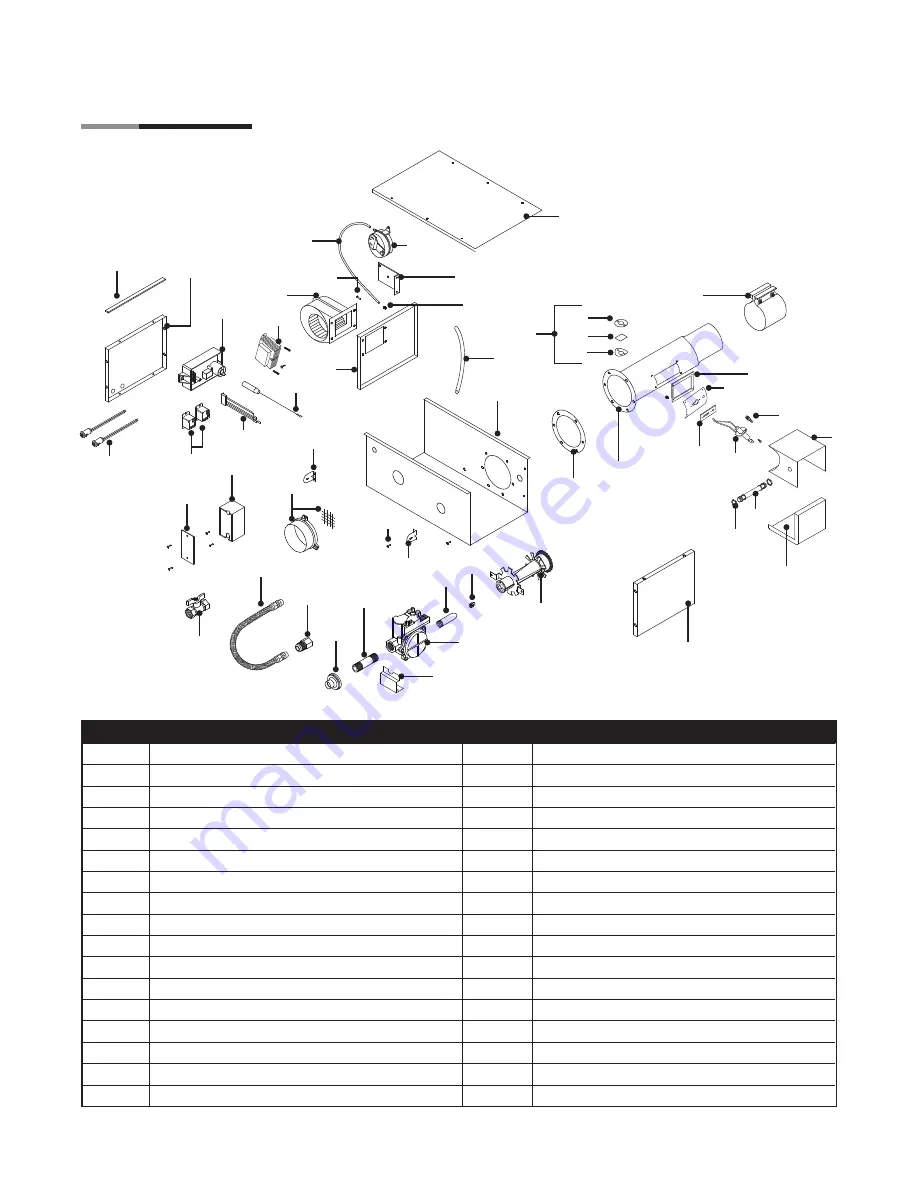
Figure 5.1
•
Burner Assembly Components
Chart 5.1 •
Parts List
* 6 feet total required to cover outer edges of the burner control box.
221
583
11
3055
321
1
NOPS
207
97
218
56C
55A
302, 302A
3051
3052
70
828
114
31B
33B
83
212
208B
TP-3140, TP-3141
223
204
201B or 3072
303
12
9
10
217
5
380, 580
15
14
16
21B
304, 804
76
31B
13
17
301
67
331
84
66
Part No. Description
Part No. Description
TP-1
Control Box Cover
TP-31B
Control Box Mounting Bracket
TP-5
Flange Gasket
TP-33B
1/2” Shut-Off Ball Valve / Inlet Tap
TP-9
Conduit Coupling
TP-55A
Fan Blower
TP-10
Conduit 4” x 1/2”
TP-56C
1/4” Atmospheric Tube (Vinyl)
TP-11
Ignitor Box
TP-65I
36” Interlocking Turbulator Baffle
TP-12
Ignitor Box Cover
TP-66
2” x 4” Outlet Box
TP-13
8 x 1/2” Self-Drilling Screw
TP-67
2” x 4” Outlet Box Cover
TP-14
Sight Glass Gasket
TP-70
Control Box Cover Gasket (per foot*)
TP-15
Sight Glass
TP-76
Rubber Grommet
TP-16
Sight Glass Washer
TP-82
Reflector Center Support (RCS)
TP-17
Sight Glass Kit
TP-83
24” Stainless Steel Flexible Gas Connector
TP-19B
4” Wire Hanger with Tension Spring
TP-84
1/2” Female / Male Flare Fitting
TP-20C 120” Aluminum Reflector
TP-97
1/4” x 1/4” Brass Int./Ext. Atmos. Barb Fitting
TP-21B
4” Standard Tube Clamp
TP-105
Aluminum Reflector End Cap
TP-26A
10 ft. Coated-ALUM Combustion/Radiant Tube TP-106
Reflector End Cap Clips (8 pcs.)
TP-26B
10 ft. Coated-AL-TI Combustion Tube
TP-113
Reflector Tension Spring
TP-26C 10 ft. Uncoated Hot-Rolled Steel Radiant Tube TP-114
Plastic Air Orifice w/ Screen (consult factory)
1325
550
826

