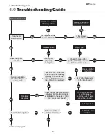
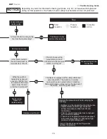
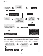
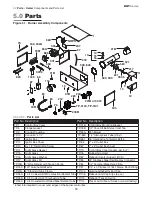
background image

19

RHT 

Series

5.0

 Parts • Heater 

Components and Parts List
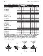
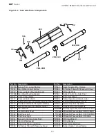
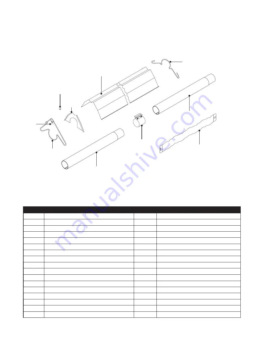
Figure 5.2 

 Tube & Reflector Components

19B

106

105

26A, 26B

21B, 220

20C

82

26A, 26C

65I

113

Part No. Description

Part No.

Description

TP-201B Burner (Tan) - consult factory

TP-550

Spark Transfer Wire - Orange

TP-204

Gas Orifice (consult factory)

TP-580

16” Burner Tube with Flange 

(with fittings)

TP-207

Pressure Switch Mounting Bracket

TP-583

DSI Igniter Plate

TP-208B Gas Valve Mounting Bracket

TP-804

Burner Control Box Outer Shell

TP-212

1/2” x 3” Pipe Nipple

TP-826

40VA Transformer

TP-217

Pressure Switch Barb

TP-828

Yellow Operational Indicator Light

TP-218

Differential Switch Vinyl Exhaust Sensing Tube TP-1325

24VAC Switching Relay (Qty 2)

TP-220

Stainless Steel Tube Clamp 

(150-200MBH)

TP-3140

Natural Gas Valve Assembly

TP-221

Spark Igniter Mounting Bracket Gasket

TP-3141

Propane Gas Valve Assembly

TP-223

Gas Manifold

TP-NOPS

Normally Open Pressure Switch 

(see below)

TP-301

Center Divider Panel

TP-264B Differential Pressure Switch 50-100 MBH

TP-302

End Panel, Left

TP-264E Differential Pressure Switch 125-150 MBH

TP-303

End Panel, Right

TP-264D Differential Pressure Switch 175 MBH

TP-304

Burner Control Box Outer Shell

TP-3051

DSI Circuit Board

TP-321

Ignition Plate Gasket

TP-3052

Wiring Harness

TP-331

Green Self Tap Ground Screw

TP-3055

Spark Igniter Electrode

TP-380

16” Burner Tube with Flange 

(no fittings)

TP-3072

Burner (Green) - consult factory

Summary of Contents for RHT-100 SERIES

Page 1: ...ty damage serious injury asphyxiation or death RHT Series Insert Manual For complete installation instructions see the Tube Heater General Manual that accompanies this Series Insert Manual For Your Safety If you smell gas Do not try to light any appliance Immediately call your gas supplier from a neighbor s phone Do not touch any electrical switch Follow the gas supplier s instructions Do not use ...

Page 2: ...al Requirements 6 Wiring 7 Specifications 10 Tube Installation Sequence 11 3 0 Operation 12 Sequence of Operation 12 Thermostat 12 Diagnostics 13 4 0 Troubleshooting Guide 14 5 0 Parts 18 Components 18 Parts List 18 Kit Contents Check List 20 Approvals 20 Limited Warranty 20 NOTE See page 10 for a list of available models and specifications ...

Page 3: ...C2 C3 None N A RHT 125 10 14 36E96 224 N MICRO 50X 117 3 PCS Harness None None None None IS22010051F5166 Grey Norton Mid 4 Gen Yellow 24V Specify TP s 240 551 552 N A N A 264E 555 201B 580 328 On Circuit Board None 40 VA Fasco Lg 50Hz 120V When Specified None None 3 T plug 2 x 4 Box 7 8 FC Flare None N A 826 55A 55B N A N A 832 66 83 19 1 5 16 TP 204 TP 44 19 1 7 16 LLWT000 None 19 1 5 16 17 1 7 1...

Page 4: ...r system clearances to combustibles for the model tube heater and configuration must be maintained Refer to Chart 1 1 below to determine the required distances for your model Clearance to Combustibles F N LLDR003 F N LLV3EP2 Orange Crescent SERVICE ACCESS PANEL IGNITER FLAME SENSE COMPARTMENT 1 Turn off gas electricity 2 Remove cover by lifting top cover upward and outward CAUTION HOT SURFACE KEEP...

Page 5: ...nd Below Top Side Side Below Top 0 Mounting Angle Side Side Below Top Model Number Mounting Angle Side Top Below Front Behind RHT 65 75 N P 20 30 40 0 9 9 6 60 45 39 8 10 60 with 1 side shield 0 29 8 6 60 with 2 side shields 0 9 9 6 60 20 ft from burner 0 7 7 6 30 RHT 100 N P 30 40 0 14 14 6 66 45 39 8 10 66 with 1 side shield 0 29 8 6 66 with 2 side shields 0 16 16 6 66 20 ft from burner 0 7 7 6 ...

Page 6: ... 1 1 amps Electrical Requirements Connecting the thermostat with a voltage other than 24V may damage the heater The RHT Series requires a 24V connection to the thermostat The RHT Series is equipped with an internal relay board A field supplied external transformer must be installed See wiring diagram Figures 2 1A B Instructions for the following are detailed in the Tube Heater General Manual Desig...

Page 7: ...e terminals required as supplied 120VAC 24VAC EXTERNAL TRANSFORMER Field Supplied L1 N observe polarity 120 Volt Power Figure 2 1 Field Wiring Diagrams A Single Heater Single Thermostat B Multiple Heaters Single Thermostat 1 2 LO HI 1 2 LO HI BURNER CONTROL BOX 1 2 LO HI BURNER CONTROL BOX BURNER CONTROL BOX L1 N PANEL GROUND 120 VAC Observe polarity PANEL GROUND PANEL GROUND NOTE If optional yell...

Page 8: ...HT Ladder Diagram B RHT Block Diagram NEUTRAL THERMOSTAT NEUTRAL VALVE GROUND HIGH VOLTAGE BLOWER MOTOR L1 120VAC N LIGHT T STAT TERMINAL GAS VALVE PRESSURE SWITCH P M H ELECTRODE ASSEMBLY 24V 120V BK BK R BK BK BL BK BK R W BL O R W G Y BL BK W Y R HIGH RELAY LOW RELAY HI M C C HI M C C NEUTRAL THERMOSTAT NEUTRAL VALVE GROUND HIGH VOLTAGE COM NO NC 120V 24V TRANSFORMER GAS VALVE N O PRESSURE SWIT...

Page 9: ...9 RHT Series 2 0 Installation This page intentionally left blank There are no alternative wiring diagrams for the RHT Series ...

Page 10: ...0 100 000 60 2 265 16 to 30 TPK F C TPK K H RHT 175 50 Nat or Prop 175 000 125 000 50 2 235 16 to 30 TPK F A TPK K G RHT 175 60 Nat or Prop 175 000 125 000 60 2 265 16 to 30 TPK F C TPK K H RHT 200 50 Nat or Prop 200 000 145 000 50 2 235 17 to 35 TPK F A TPK K G RHT 200 60 Nat or Prop 200 000 145 000 60 2 265 17 to 35 TPK F C TPK K H Chart 2 1 Specifications Specifications Package ID Description W...

Page 11: ...ly Located between 1st and 2nd 10 ft tube sections Baffle Location Burner Control Box with 16 Burner Tube Primary Combustion Chamber Tube Secondary Aluminized Steel Combustion Chamber 150 175 MBH models only Aluminized or Hot rolled Steel Radiant Emitter Tube 20 Foot 50 Foot 60 Foot 30 Foot 40 Foot Stainless steel clamp location on 150 200 MBH models P N TP 220 Aluminized steel secondary combustio...

Page 12: ...g to lockout mode The control can be reset by briefly interrupting the power source Two Stage Running Circuit High fire operation is actuated by the thermostat sending a 24VAC signal to the high fire relay The energized coil of the relay is closed allowing 24VAC to continue onto the high fire of the gas valve Thermostat NOTE Different thermostats operate according to their particular features Refe...

Page 13: ...e sense etc the heater will enter a soft lockout period for 30 minutes and then attempt to light three more times before entering Hard Lockout mode Hard Lockout If proof of flame is not established a component failure occurs or blockages are evident the heater will enter hard lockout If lockout occurs the control can be reset by briefly interrupting the power source Figure 3 1 LED Operation Indica...

Page 14: ...s Replace igniter Yes No Find the source of the electrical problem Check the gap on the igniter Is the gap between 3 16 in and 1 4 in No Adjust gap Yes No Yes No During the ignition trial does the gas valve open Yes Test for 24VAC at the gas valve during valve opening typically 10 seconds after power to the heater Is there 24VAC to the valve No Yes Is 120VAC being sent to the transformer No Does t...

Page 15: ...tch is a normally open switch and is located in the air chamber Temporarilly place a jumper across the terminal of the switch Does the igniter spark Yes Replace the pressure switch after verifying the following Baffle s is in the tube farthest from the burner Heater blower squirrel cage intake and exhaust are clean and free from dirt and obstructions The 4 in dia air intake pipe does not exceed 20...

Page 16: ...ed properly Fluctuating gas pressure No Adjust gap Does the burner stay on No Does the heater stay on until the call for heat ends Yes Yes Troubleshooting ends Is the heater properly grounded Is the polarity correct Yes No No Yes Yes No Correct problem No Flame Current Check Single Spark Sense To measure flame current disconnect input voltage then insert a 0 50 μA DC meter and capacitor in series ...

Page 17: ...es W C natural gas or 10 inches W C propane gas If the indicator light is not illuminated it is faulty and should be replaced If the manifold pressure ranges from 2 3 to 2 8 inches W C natural gas model dependent and 6 0 to 7 5 inches W C propane gas model dependent the heater is in low fire mode and the troubleshooting steps described below should be followed Were the gas lines purged of air Yes ...

Page 18: ...TP 65I 36 Interlocking Turbulator Baffle TP 12 Ignitor Box Cover TP 66 2 x 4 Outlet Box TP 13 8 x 1 2 Self Drilling Screw TP 67 2 x 4 Outlet Box Cover TP 14 Sight Glass Gasket TP 70 Control Box Cover Gasket per foot TP 15 Sight Glass TP 76 Rubber Grommet TP 16 Sight Glass Washer TP 82 Reflector Center Support RCS TP 17 Sight Glass Kit TP 83 24 Stainless Steel Flexible Gas Connector TP 19B 4 Wire H...

Page 19: ...TP 218 Differential Switch Vinyl Exhaust Sensing Tube TP 1325 24VAC Switching Relay Qty 2 TP 220 Stainless Steel Tube Clamp 150 200MBH TP 3140 Natural Gas Valve Assembly TP 221 Spark Igniter Mounting Bracket Gasket TP 3141 Propane Gas Valve Assembly TP 223 Gas Manifold TP NOPS Normally Open Pressure Switch see below TP 301 Center Divider Panel TP 264B Differential Pressure Switch 50 100 MBH TP 302...

Page 20: ...End Cap Clips TP 33B 1 2 Shut Off Valve Ball Valve Inlet Tap TP 83 24 Stainless Steel Flexible Gas Connector Kit Contents Check List RHT Series Kit Contents TP 82 4 Reflector Center Support RCS NOTE One 4 stainless steel tube clamp P N TP 220 is provided for each 150 000 200 000 BTU model Place as shown on page 11 Not included with models installed with yellow control cord 2014 Detroit Radiant Pro...

Reviews: