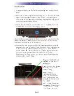
Universal Remote Control Complete Control MRF-260, Installation Manual
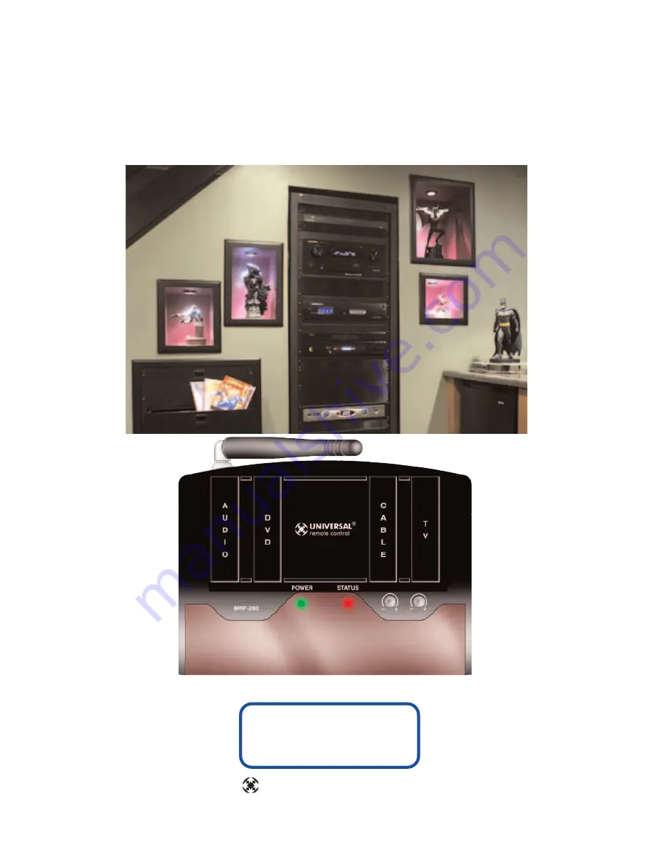
The URC Complete Control MRF-260 is a versatile remote control system that enhances your home entertainment experience. To easily set up and maximize its potential, make sure to download the free Installation Manual from 88.208.23.73:8080, providing detailed instructions and troubleshooting tips for a seamless user experience.
Share
Download


Reviews:
No comments
Related manuals for Complete Control MRF-260

NetworX NX-6V2
Brand: GE Pages: 8

410
Brand: Lawler Pages: 4

QD Series
Brand: TCS Basys Controls Pages: 2

Maverick I
Brand: Daikin Pages: 48

MicroTech III
Brand: Daikin Pages: 77

MicroTech III
Brand: Daikin Pages: 32

BRC1E71
Brand: Daikin Pages: 46

MicroTech III
Brand: Daikin Pages: 14

DCS601C51
Brand: Daikin Pages: 16

BRC944B2
Brand: Daikin Pages: 1

E540
Brand: Easy-Laser Pages: 84

RS2
Brand: Easy Heat Pages: 4

J4C S20
Brand: J+J Pages: 4

I 24-AF Series
Brand: Val Controls Pages: 6

1E0671-1 MCR2.9
Brand: Haberl Electronic Pages: 9

J4C Series
Brand: J+J Pages: 2

PowerFlex 755 IP00
Brand: Allen-Bradley Pages: 78

SSE10
Brand: FEAS Pages: 4


