IIR
R O
O
U
UT
TP
PU
UT
T
controls the Line Outputs for Flashers
affixed to the front panels of components.You
can opt to either send IR Commands to:
ALL - The commands are sent to all of
the Flashers
1-6 - Just the specified Flasher receives
the IR commands (Useful when
identical TV’s or VCR’s are utilized
in the system)
A
Ad
dd
diin
ngg M
MR
RF
F--2
20
00
0 R
Re
ecce
eiivve
errss,, C
Co
on
nggu
urriin
ngg IID
D#
#’’ss aan
nd
d F
Frro
on
ntt B
Bllaasstte
errss
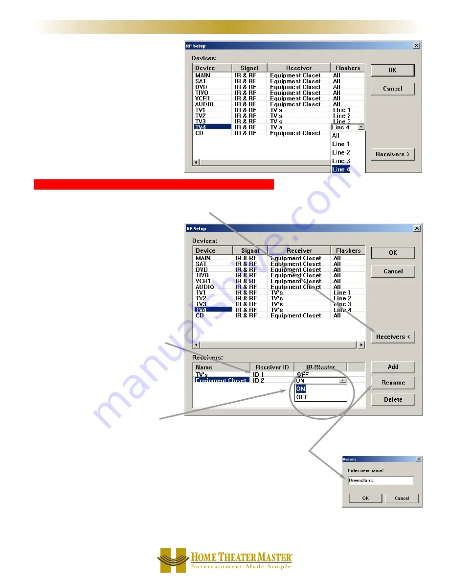
To add a new receiver to the list, to change the Receiver ID# of your existing receiver or to enable/disable the Front Blaster,
click on the Receiver button of the RF Control window.
4
49
9
M
MX
X--8
80
00
0 R
RF
F C
Co
on
nttrro
oll
M
X
8
0
0
M
X
7
0
0
M
X
2
0
0
R
E
M
O
T
E
S
You may rename areceiver to something
more descriptive by first selecting the
receiver’s name cell, then clicking on the
Rename button.
If you want the Front Blaster turned OFF on
any receiver, reset it by clicking on the correct
CELL and selecting OFF.
NOTE: In some installations, the MRF-200’s
Front Blaster is so powerful that it can overload
nearby components and give poor or intermit-
tent operation. Try re-positioning the MRF-200
to reduce the power flooding the cabinet or turn
the Front Blaster off.
After pressing the Receivers button, the RF
Control Window will enlarge revealing the
Receiver configuration options. Again, you click
on a cell to adjust.
The Receiver ID cells enable you to change the
ID# of each receiver, so that commands for one
will be ignored by the other if set to different
ID’s.
Note that in this system, the MRF-200 in the eq
uipment closet is set to ID#2 and the MRF-200 con-
nected to the identical TV’s is set to ID#1.


